 This is the second part of the Allsky cycle, and I want to describe powering and protection of this device.
Please read the first part to get basic information about this project.
Since the camera box is connected through only one Ethernet cable, it’s important to deliver via this cable enough power for all internal devices. This cable’s length is more than 15 meters, so I decided to use a 19v laptop power adapter and custom down-converter inside the camera to get 12, 5, and 3.3 volts.
For power delivery, used free Ethernet pairs of wires: blue and brown.
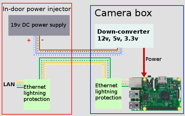
The total cable length is 15 meters, and it’s vital to protect the device from static electricity, electromagnetic interference, and voltage spikes.
Protection circuits
For better reliability, I used two Ethernet protection circuits on both sides of the cable.
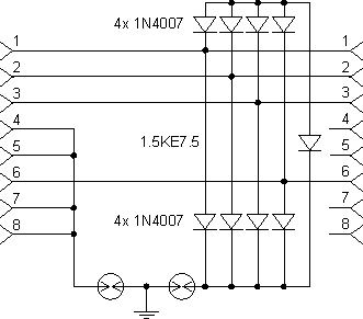
Diode 1.5Ke 7.5 is pretty fast and opens when the line’s voltage exceeds 5-6 volts. This voltage is draining on the Ground.
Two spark gaps are arrestors from Epcos. You can bypass the right arrester with a megaohm resistor for better performance and constant current flow.
Both parts of the protection circuit should be properly grounded.
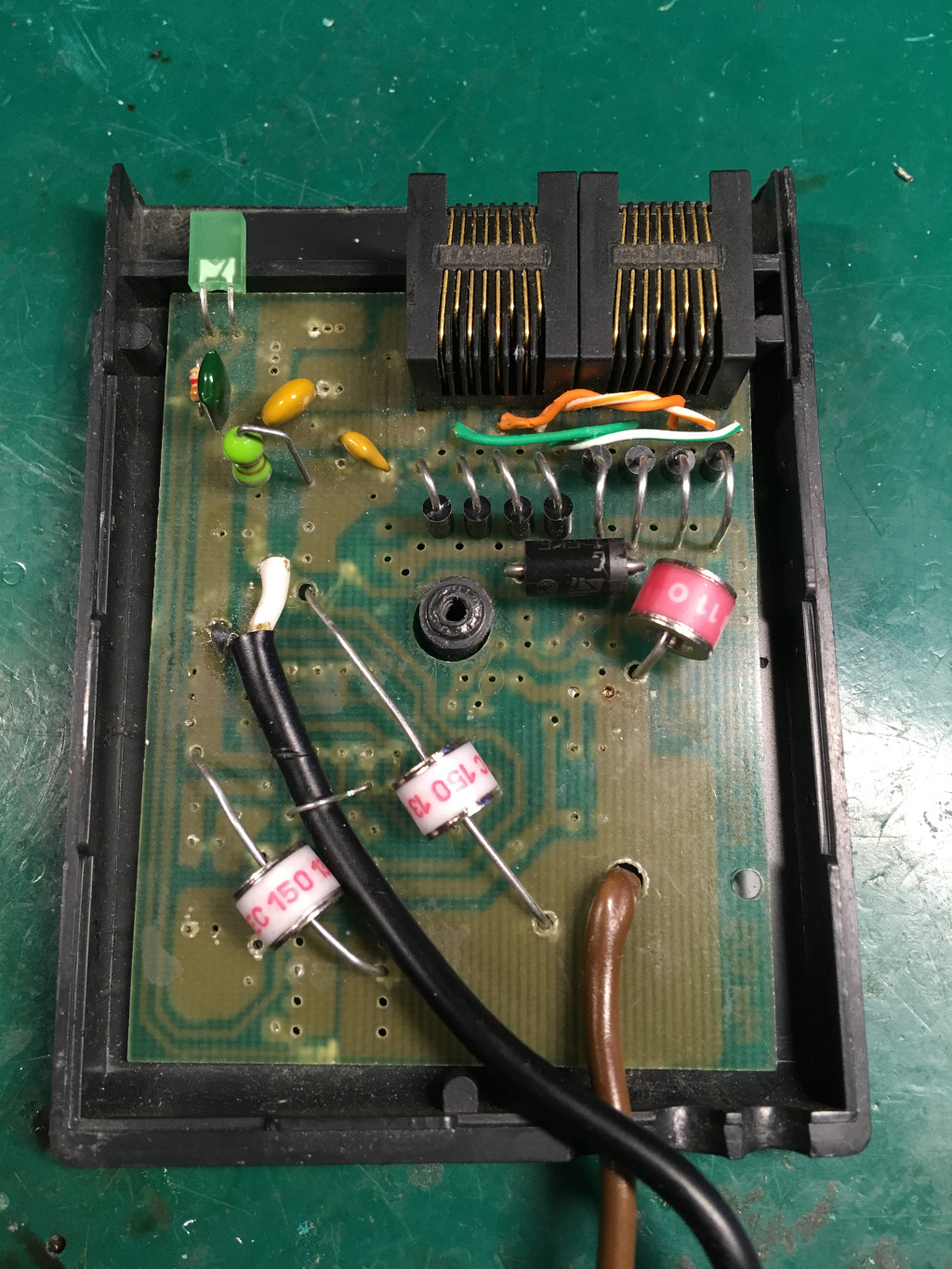
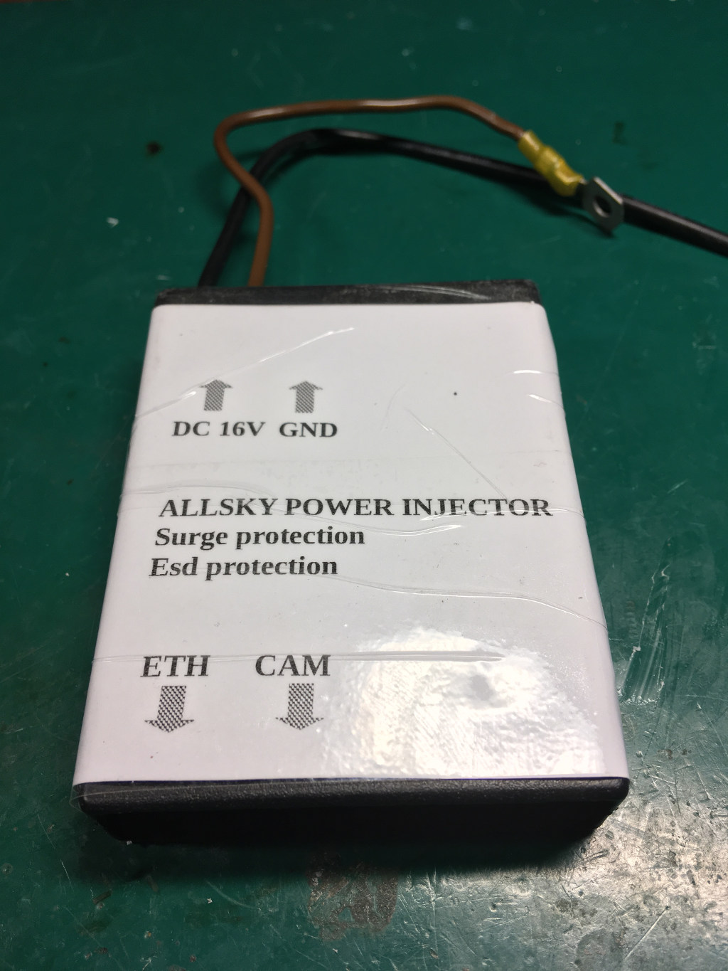
The in-door power injector is built using an old power splitter from telecommunication equipment. Actually, there is only a plastic case and an old PCB with all the removed old components.
You can see the protection circuit near the 8P8C connectors.
A power supply is just directly connected to the brown and blue Ethernet pairs using few bypass capacitors. Both power wires are also grounded via arresters.
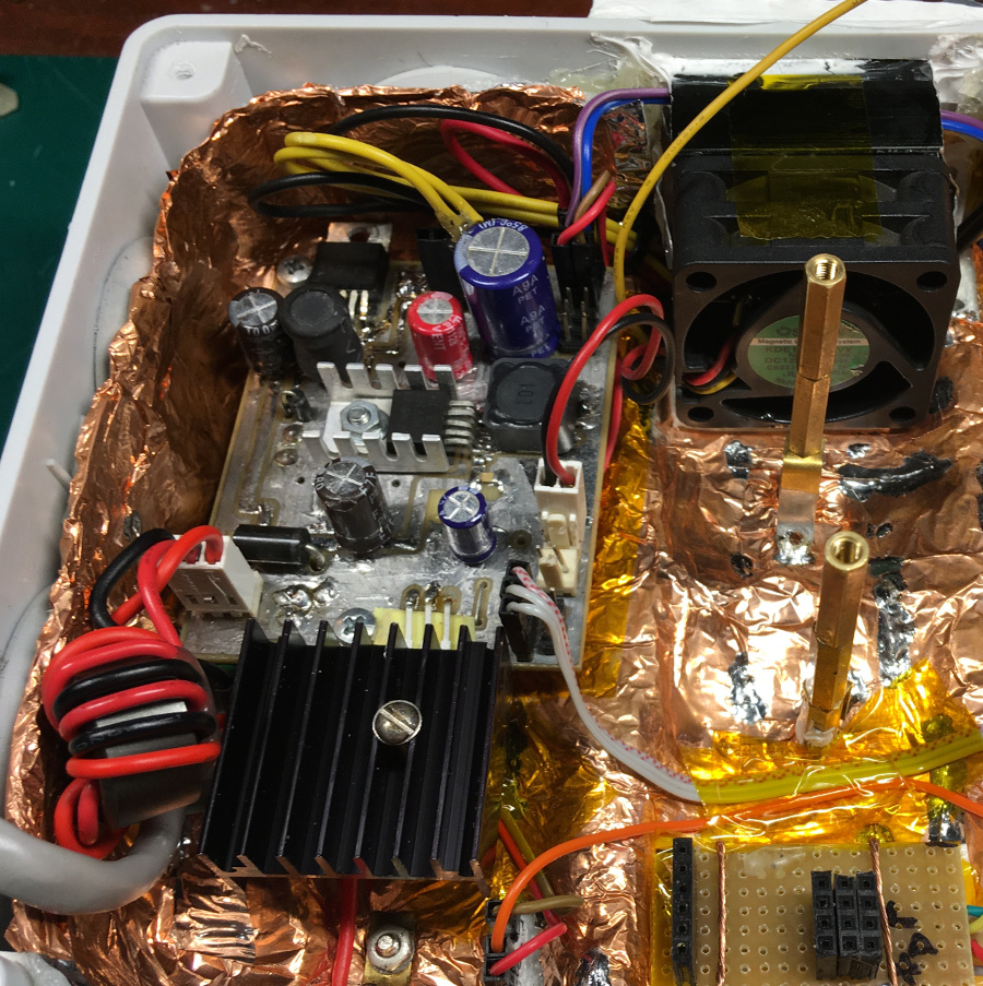
Protection circuit inside camera box.
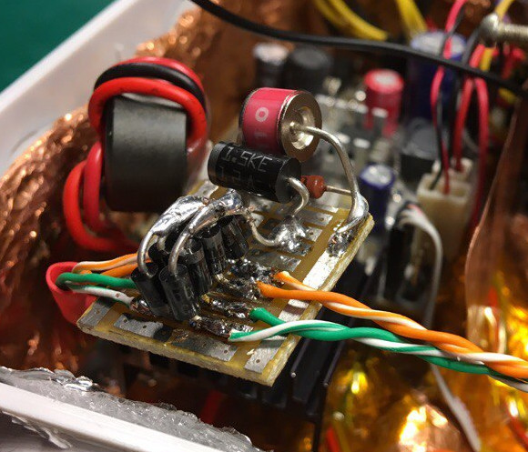
Connected directly to the grounding screw on the bottom.
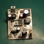
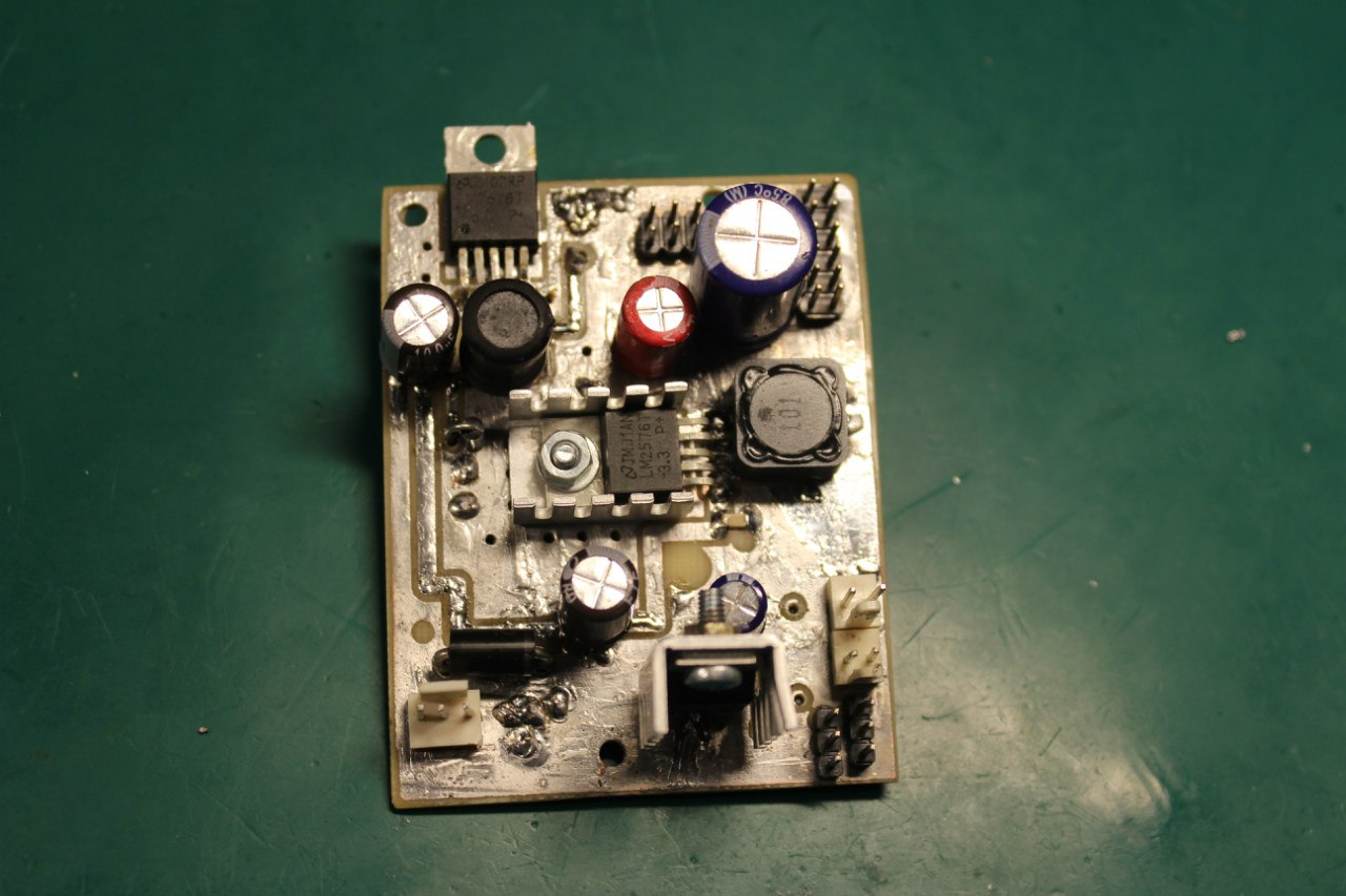
Power down-converter
This module built using two impulse converters, LM2576. This device is simple to use and requires only a few external components.
12v is used for PWM-controlled coolers and the IRIS motor.
This converter is linear 78S12, which can provide enough current without overheating. All the heat of this converter is also used for warming up the air inside the camera box.
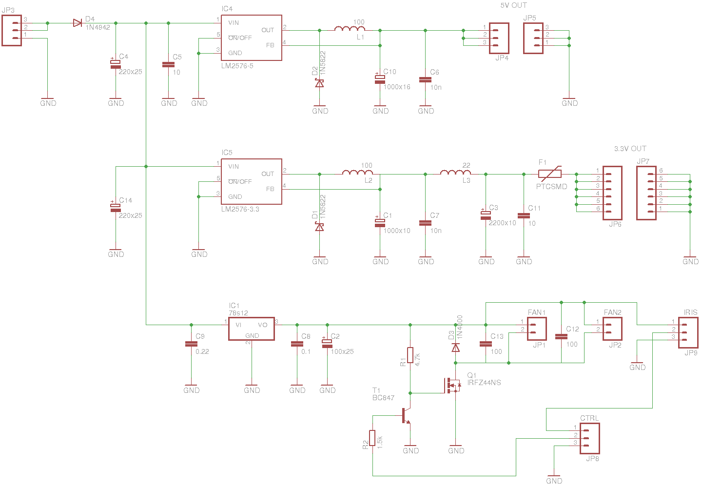 T1 and Q1 is a driver for the coolers. The input signal is PWM from the Raspberry. It’s a good idea to put some additional inductors and capacitors near the fans. Values should be hand-picked depending on how stable your fans on low rpm. In my case used 100 microhenry and 220 microfarads.
All circuit is placed on two-layer handmade PCB.
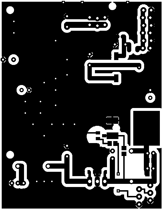
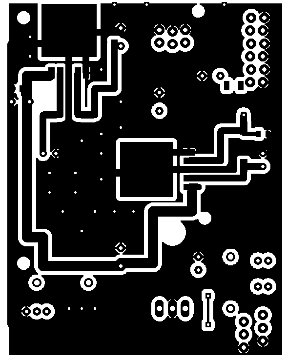 Both LM2576 is soldered directly to the boards, which acts as a good radiator, so all components are in a good thermal state under any conditions.
 3.3v is used for the Raspberry and all I2C devices. 5V is connected directly to a USB camera cable bypassing the Raspberry board and additional connectors. This voltage is also required for the CPU and should also be connected to the Raspberry 5v line.
End of part 2.
Thanks for reading! 🙂
2 thoughts on “Autonomous Allsky camera with Raspberry PI. Part 2: powering and lightning protection”