 RS485 is a standard for use in serial communications systems. Electrical signaling is balanced, and multipoint systems are supported. This communication standard is used in a wide range of computer and automation systems. RS-485 is used as the physical layer underlying many standard and proprietary automation protocols used to implement Industrial Control Systems, including the most common versions of Modbus and Profibus, also used to build automation as the simple bus wiring long cable length is ideal for joining remote devices. It may be used to control video surveillance systems or interconnect security control panels and devices such as access control card readers.
This article will show how to build a simple and reliable USB to RS485 adapter with galvanic isolation and ESD protection.
Take a look at the second version of this adapter.
RS-485 is not a protocol; it’s simply an electrical interface. Although many applications use RS-485 signal levels, the speed, format, and protocol of the data transmission are not specified by RS-485.
This line transmits digital information between multiple locations. Data rates can be up to, and sometimes greater than, 10Mbps. RS-485 is designed to transmit this information over significant lengths, and 1000 meters are well within its capability. The distance and the data rate with which RS-485 can be successfully used depend a great deal on the system’s wiring.
You can read more about RS485 networks and wiring in this great article from Maxim.
It’s straightforward to convert the RS485 line to the unbalanced UART interface using a special IC. Many vendors provide different solutions at different prices. As usual, the simplest solutions are pin-to-pin compatible and can be easily replaced.
In my projects, I’m using ADM485 and MAX485, which are quite identical. Both chips are very low cost, easy to use, and easy to solder.
These devices are half-duplex transceivers, so you need to manipulate I/O states using 2 and 3 pins of the chip.
Pin 2 (RE) – Receiver Output Enable. A low level enables the receiver output, RO. A high level places it in a high impedance state. RX state.
Pin 3 (DE) – Driver Output Enable. A high level enables the driver differential outputs, A and B. A low-level places it in a high impedance state. TX state.
USB and isolation part is identical to my eqmod adapter. FT232 + ADUM1201 is the best choice. The second part of the ADM1201 is connecting directly to the 485 chip.
What about the powering of the isolated part?
There are perfect solutions on the market. For example – DC-DC converters from Traco power, like TMV0505S. This converter is 5v input and stable 5v output, providing isolation up to 3000 volts DC.
The transceiver state can be switched using a high-speed optocoupler.
Here is the schematic of the device.
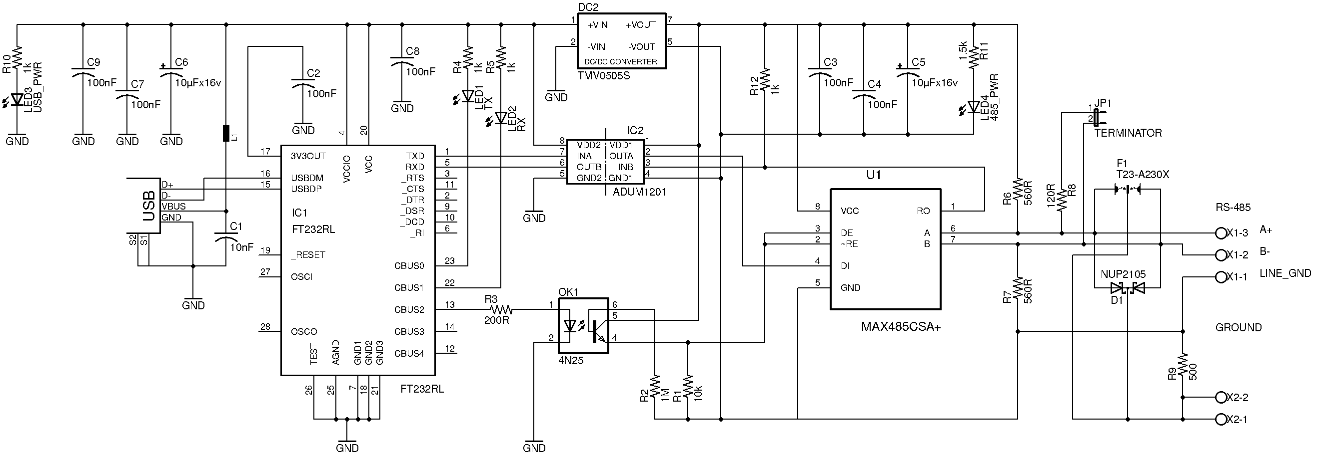
As you can see left part of the schematic is almost identical to the eqmod schematic. Please refer the previous article for details.
OK1 4N25 is a high-speed optocoupler used to driver 2 and 3 pins of the MAX/ADM485. CBUS2 of the FT232 controls the photodiode. Please check the FT232 datasheet, section “3.5 CBUS Signal Options”.
Resistor R2 is used to stabilize the phototransistor and avoid false positives of the optocoupler.
D1 NUP2105 is protection diodes designed for RS485/CAN buses. These diodes can protect networks from ESD and other harmful transient voltage events.
F1 is an arrestor from Epcos and can help to protect the device from larger voltage spikes. Of course, this device should be properly grounded via X2-1 and X2-2 terminal. Without grounding, all protection circuits is useless.
R8 is an optional termination resistor that can be disconnected by the JP1 jumper. This resistor should be connected if this adapter is placed on the line ending point.
X1-1 is a common terminal and can be connected to your cable’s free pairs (in case of using a standard ethernet cable). This line is grounded via a 1M resistor to avoid strong currents due to the wires’ antenna effect.
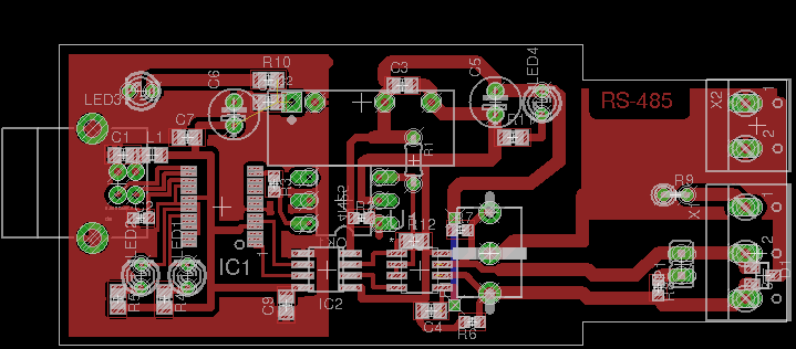
Proposed PCB layout, single-layer board.
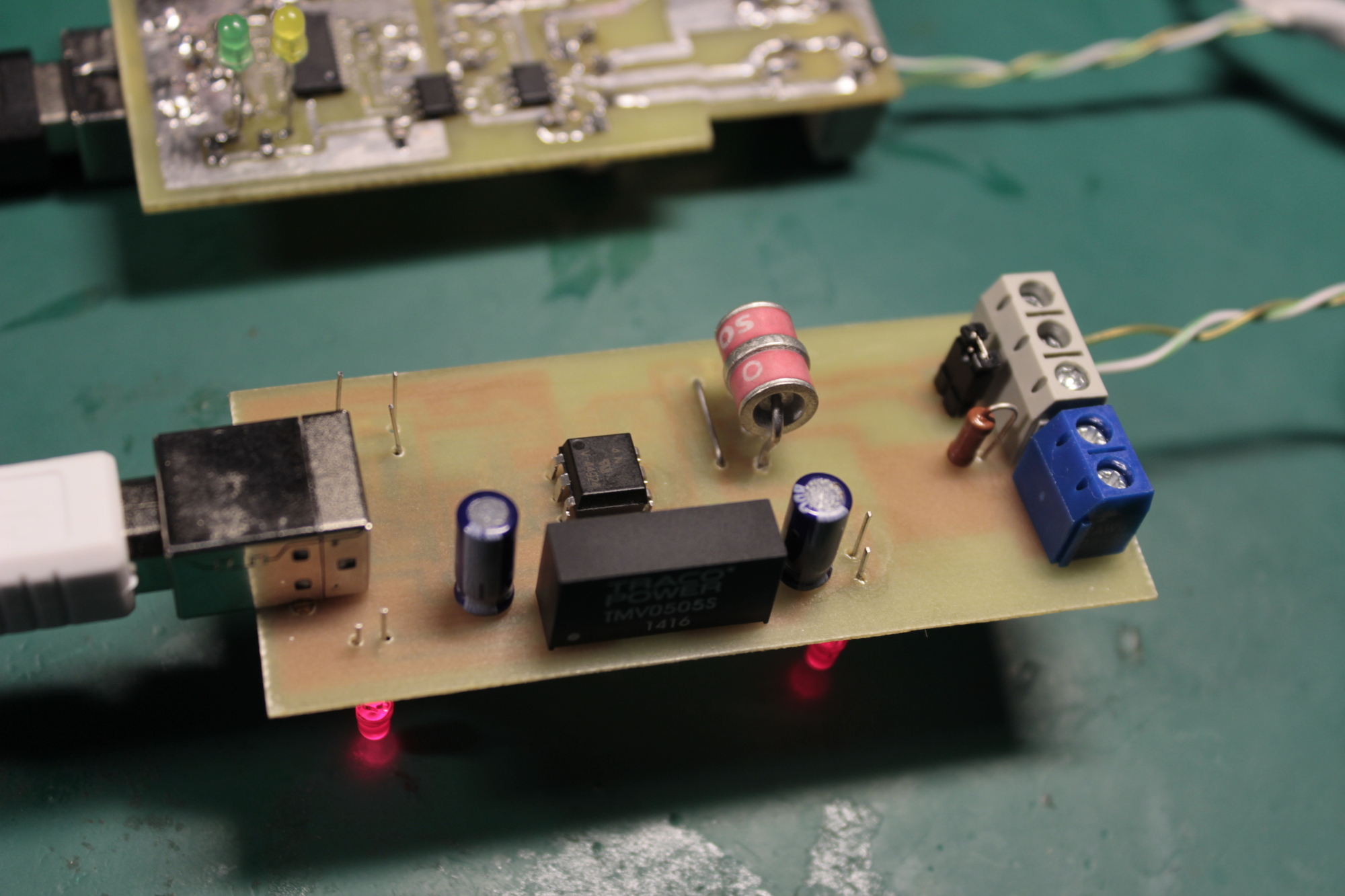
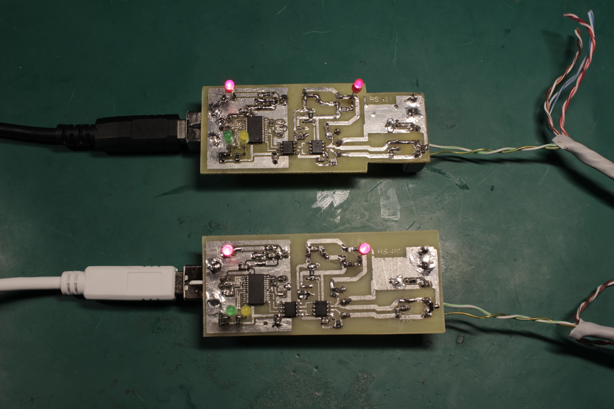
![]() And finished device PCB.
And finished device PCB.
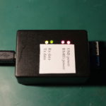
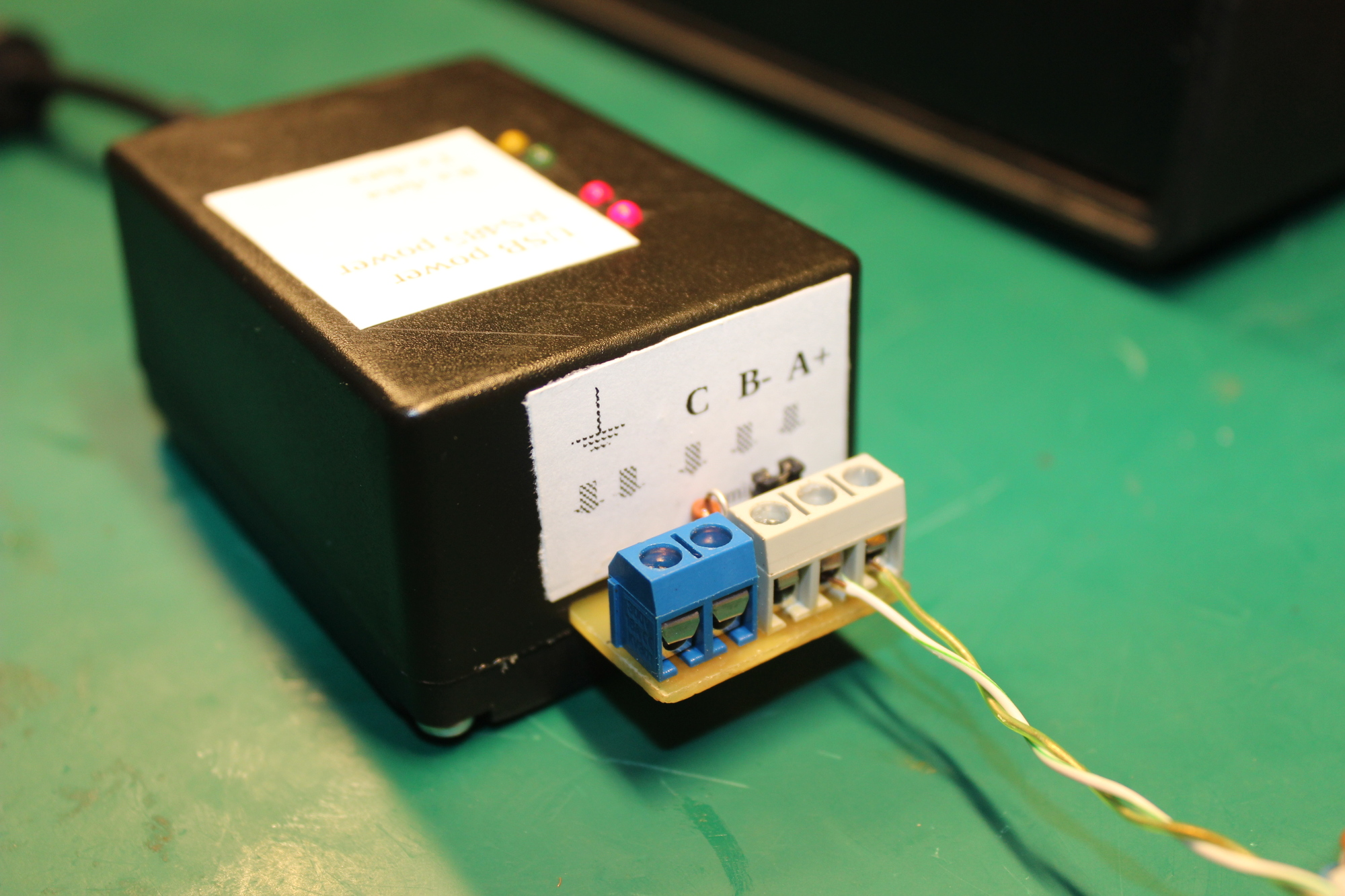
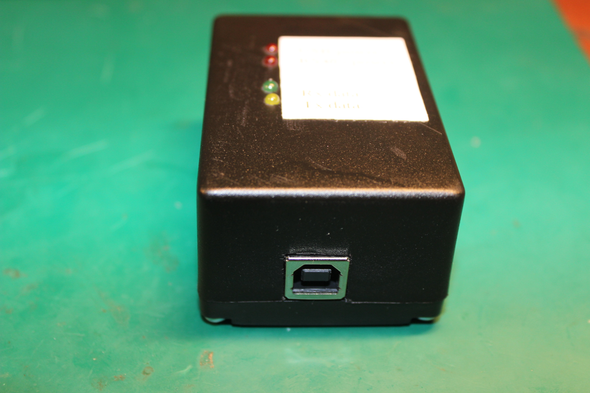
 In plastic case:

 Thanks for reading!
2 thoughts on “Isolated USB to RS485 adapter”