
Sure, it would be great to do the same thing with the new Starlink router gen2. It’s not easy to get new hardware, but why should this stop the fun?
Do I have the new Starlink router?
Unfortunately, I don’t have the new router yet. But I have a photo of the router!

Big thanks to Phil from the Ingineerix channel! He was kind enough to disassemble his Starlink router and take many photos for me of the router’s internals.
Also, many thanks to SpaceX for releasing the GPL part of the router firmware. Let’s see what we can get from photos and the code repository.
Router overview
There is no built-in Ethernet port, which is not the best solution. Users should use an external Ethernet adapter. I made a detailed review and analysis of this adapter.
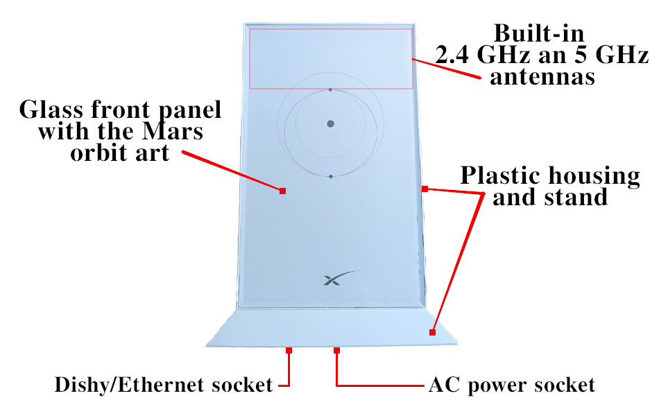
Reported that it’s tough to remove the front glass panel.
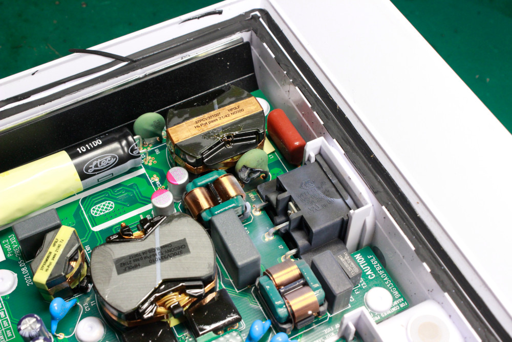
Power supply
Under the front panel, we can find the mainboard, power supply, and heatsink plate.
Here is router internals with the mainboard removed.
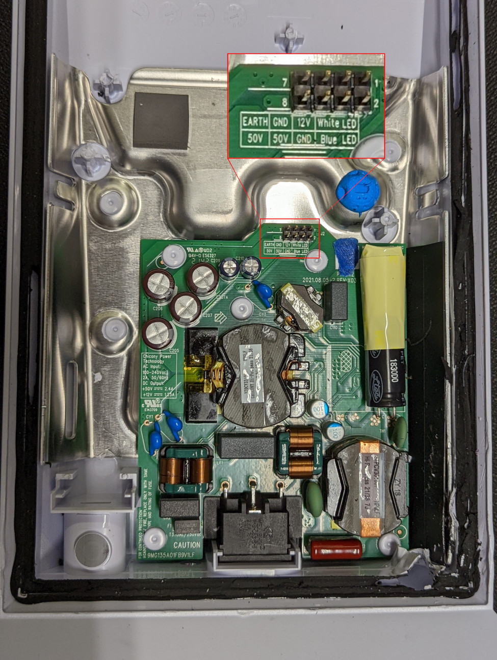
The power supply is made by Chicony and produces 50V 2.4A for the Dishy and 12V 1.25A for the router itself.
The massive metal plate cools the router CPU and radio.
Mainboard
All router components are placed on a single side of the PCB.
The PCB has an odd shape to fit inside the housing with the power supply. I’m not sure that this positively affects production costs and the amount of waste.
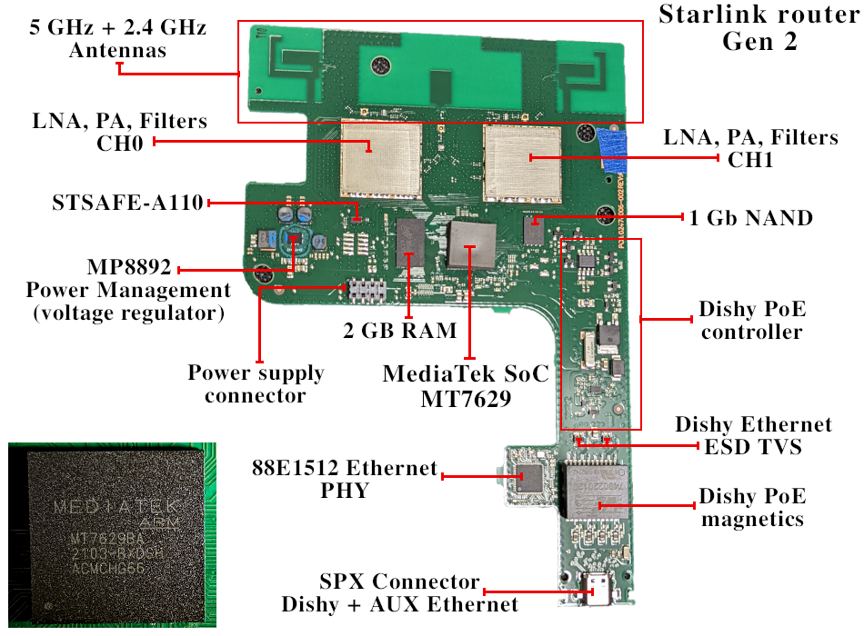
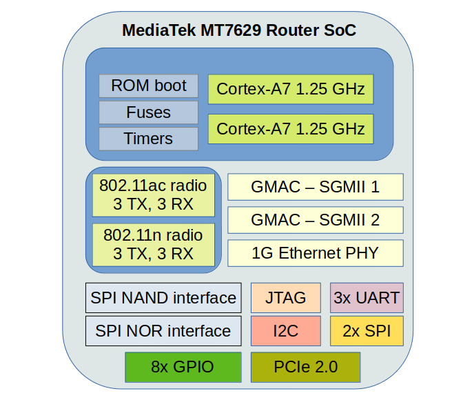
MT7629 SoC
It’s hard to find detailed information about this chip, but we can get some information from the sources repository and Google.
MT7629 it’s a dual-core ARM Cortex-A7 + MT7615-compatible 3-chain radio. Plus built-in 1G Ethernet PHY and two SGMII interfaces for external PHYs/switch.
WiFi up/down script: openwrt/package/mtk/drivers/wifi-profile/files/mt7615e.lua
Radio calibration data: openwrt/package/mtk/drivers/wifi-profile/files/mt7629
3938 CONFIG_first_card_name="MT7629"
3939 CONFIG_first_card_profile_path="/etc/wireless/mediatek/mt7629.1.b0.2g.dat;/etc/wireless/mediatek/mt7629.1.b1.5g.dat"
3940 CONFIG_first_card_init_script="/lib/wifi/mt7615e.lua;/lib/wifi/mt7615e.lua"
3941 CONFIG_first_card_init_compatible="mt7615e;mt7615e"
Plus, MediaTek declares this SoC as an inexpensive all-in-one solution for WiFi routers.
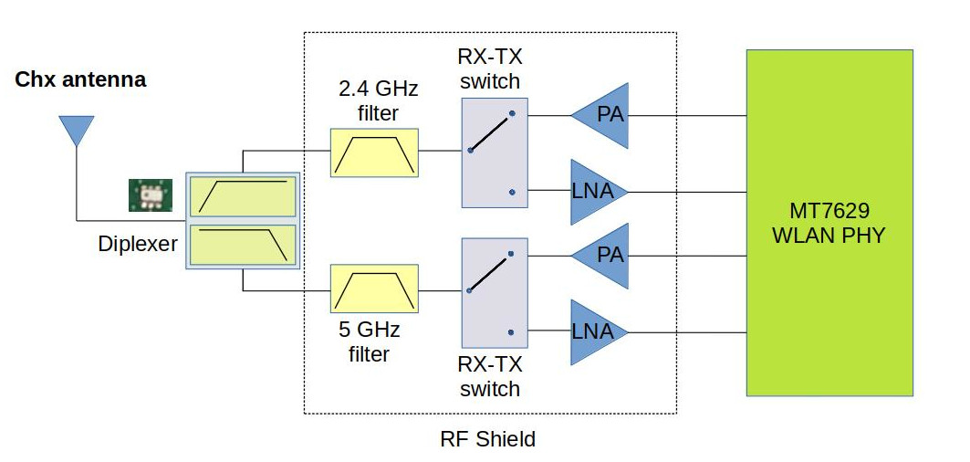
RF front end
It’s unknown what exactly is under those RF shields. But since the SoC contains a fully integrated WLAN, there are nothing more than Power Amplifiers, Low Noise Amplifiers, Filters, and Switches inside cans.
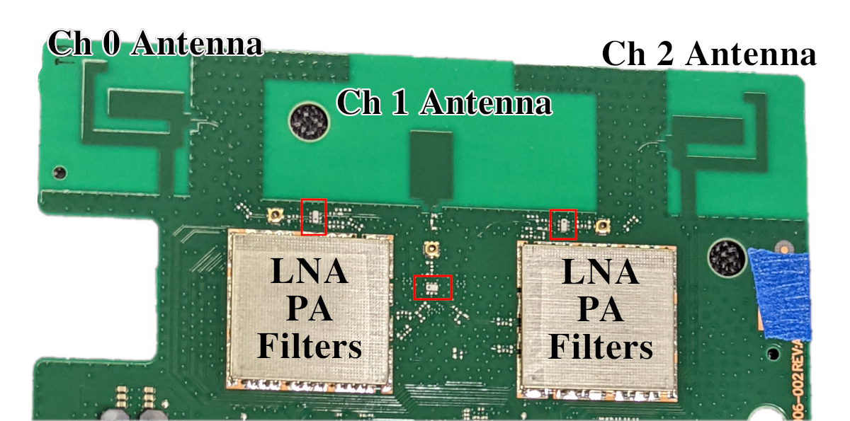
Ch0 and Ch2 antennas design was derived from the original router.
But this is a 3×3 (3 TX, 3 RX) MIMO radio. That’s why we have a third CH1 antenna here. It’s a simple patch antenna.
The new antenna layout helps to create spatial diversity for the optimal MIMO operation. This is definitely better than it was in the original router.
Three identical channels:
WiFi characteristics of the system:
2.4 GHz 802.11n 3×3 MIMO
Channel bandwidth, MHz: 20, 40
5 GHz 802.11ac 3×3 MU-MIMO
Channel bandwidth, MHz: 20, 40, 80
Please note that this is just a MAC table size of the chip. This means that this Access Point can hold up to 255 connected clients simultaneously. But this doesn’t mean that all 255 clients will work effectively. Of course, they don’t.
Tx power and sensitivity
The SoC built-in integrated PA can output up to 23.5 dBm at 5GHz.
RX sensitivity is around -94 dB.
It’s unknown what’s under those RF cans, so we don’t know the real characteristics of the RF front. I expect higher output power around 25-27 dBm and a similar (or less) RX sensitivity around -94 -90 dB.
In general, it’s a good and modern WiFi access point.
Ethernet
There are two Ethernet lines. The first one is WAN, and it’s used for the Dishy connection. The WAN interface uses SoC built-in Ethernet PHY. The only external components are powerful PoE magnetics and capacitors.
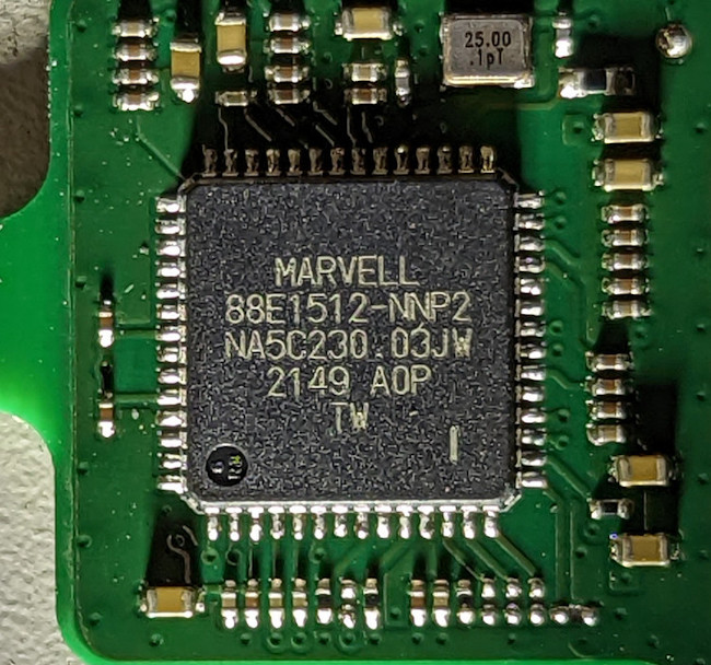
Additional external PHY 88E1512 supports the LAN interface. This is the Alaska-series PHY from Marvell. There is no Ethernet magnetics on the board.
This PHY drives the transformer inside the external Ethernet adapter.
Dishy PoE controller
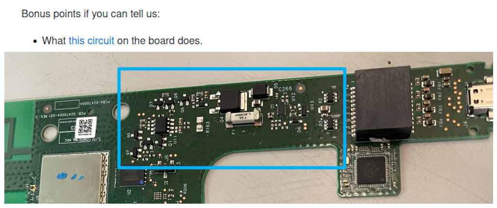
Here is a close-up mosaic photo of this area:
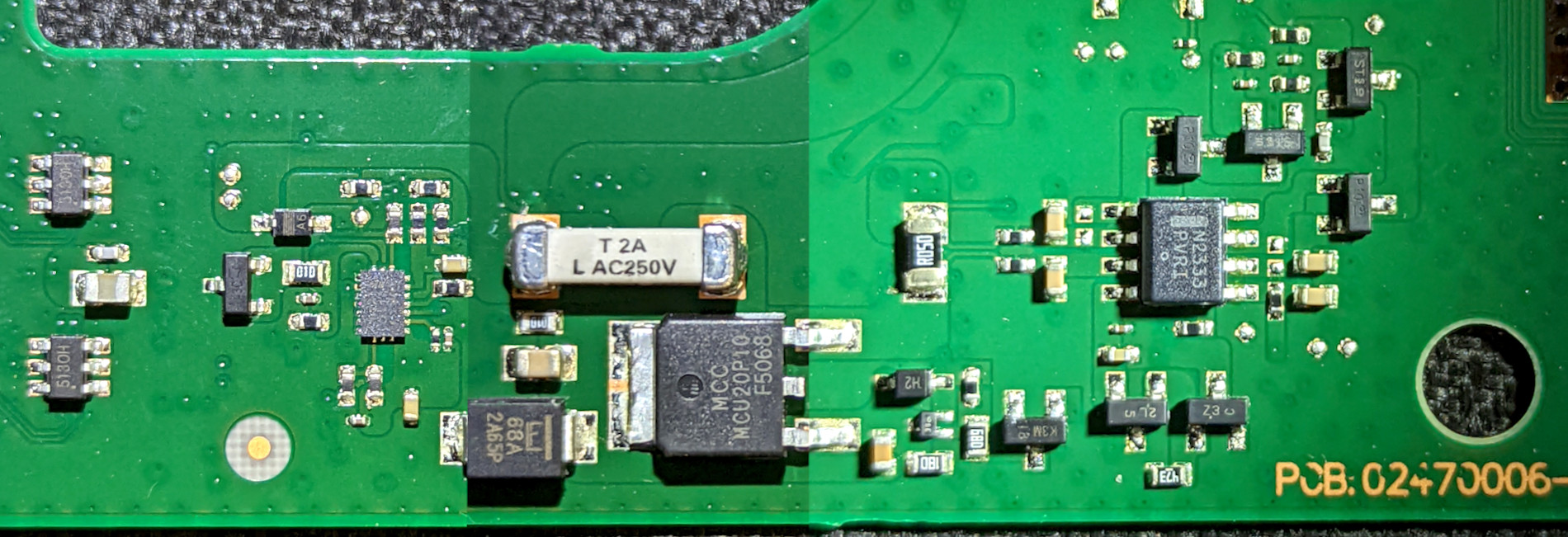
Unfortunately, I couldn’t find any information about the PoE PSE controller. I suspect that it might be something from the LTC lineup. It might be even LTPoE++. Not sure.
On the right, there is an operational amplifier and many transistors.
A big 0.05 Ohm SMD resistor, it’s a definitely current shunt. This means that the operational amplifier it’s a current measurement circuit.
Basically, the operational amplifier measures voltage difference across the shunt terminals. Due to high impedance, there is no current flow to the operational amplifier input. It’s all about only the voltage difference.
Typically, the current shunt is connected to the PoE controller directly. But, in this case, they decided to use an external amplifier for some reason. It might be the requirements of the PoE controller IC.
Or, all of this might be an effect of the chip shortage 🙂
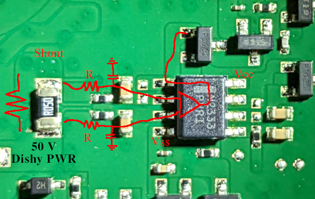
Interesting to note that the Vss pin of the operational amplifier is not connected to the ground directly. An additional circuit that “lifts” the ground for about 0.5 V allows the amplifier to measure lower values, down to 0 V.
Please excuse the crudity of these schematics. I didn’t have time to build it to scale or paint it.
Sure, there are a lot of unknowns. I don’t have the board, so I can’t trace all the lines. Also, I couldn’t identify some components. Plus, there might be incorrectly identified components.
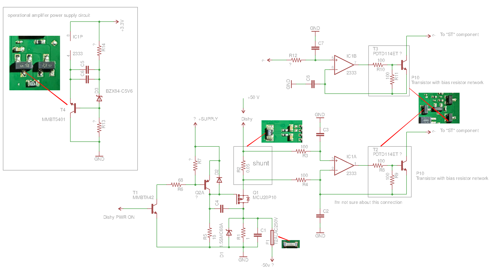
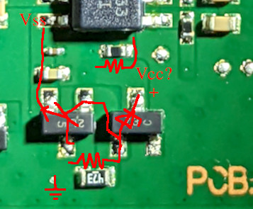
I marked unknown lines and questionable components with the “?” symbol.
Q1 MOSFET switches 50V supply for the Dishy. There is a driver circuit on two transistors. It’s always important to drive power MOSFET properly.
“Dishy PWR ON” should be connected to the PoE controller, so the 50V is applied only when the controller detects the connected PD controller on the other side (Dishy).
The operational amplifier channel 1 measures Dishy current on 0.05 Ohm shunt.
I don’t know what the second opamp channel is doing. Its non-inverting input is connected somewhere.
Both channels’ outputs are connected to the transistors. This circuit looks like an emitter follower. I couldn’t identify two components marked as “ST”. It might be some MOSFET, so the emitter follower regulates the current flowing through those MOSFETs.
Finally, this circuit should be connected to the PoE controller. It’s hardware protection against short circuits and other problems with Dishy.
Sure, some lines may be connected to the SoC to monitor the voltage/current from the software.
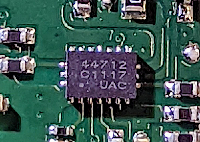
STSAFE
There is one more question in the Starlink repository:
What the device at I2C address 0x20 does.
We know from the previous article that this device is a STSAFE-A110 security/auth chip. This chip is doing the same job in the new router, plus now it’s a part of the boot process.
The STSAFE, besides providing the cert and signing capabilities that
authenticates our device as a genuine SpaceX device, also has extra zones.
We have repurposed zone 6 to store a 32bit boot counter. This counter is used to
determine whether to boot set 0 or 1 of our FIPs and Kernels. This builds in
redundancy in the event one set is inoperable. The parity of the counter is
used to determine the side. The boot counter is also communicated to the next
boot loader (U-boot) by storing it in the TRANSFER_LEN register of the i2c
MMIO (this store now happens right after select_boot_partition() returns).
This was the easiest way to pass the parameter with minor modifications to
how ATF crawls the bootloader chain.

Zones 7 and 8 of the STSAFE contain built-in decrementing counters. These
counters are used for anti-rollback functionality (the rest of the system
treats the anti-rollback counter as incrementing, so the revoked version is
"flipped" by subtracting itself from 500,000, the initial value of the
STSAFE's decrementing counters).
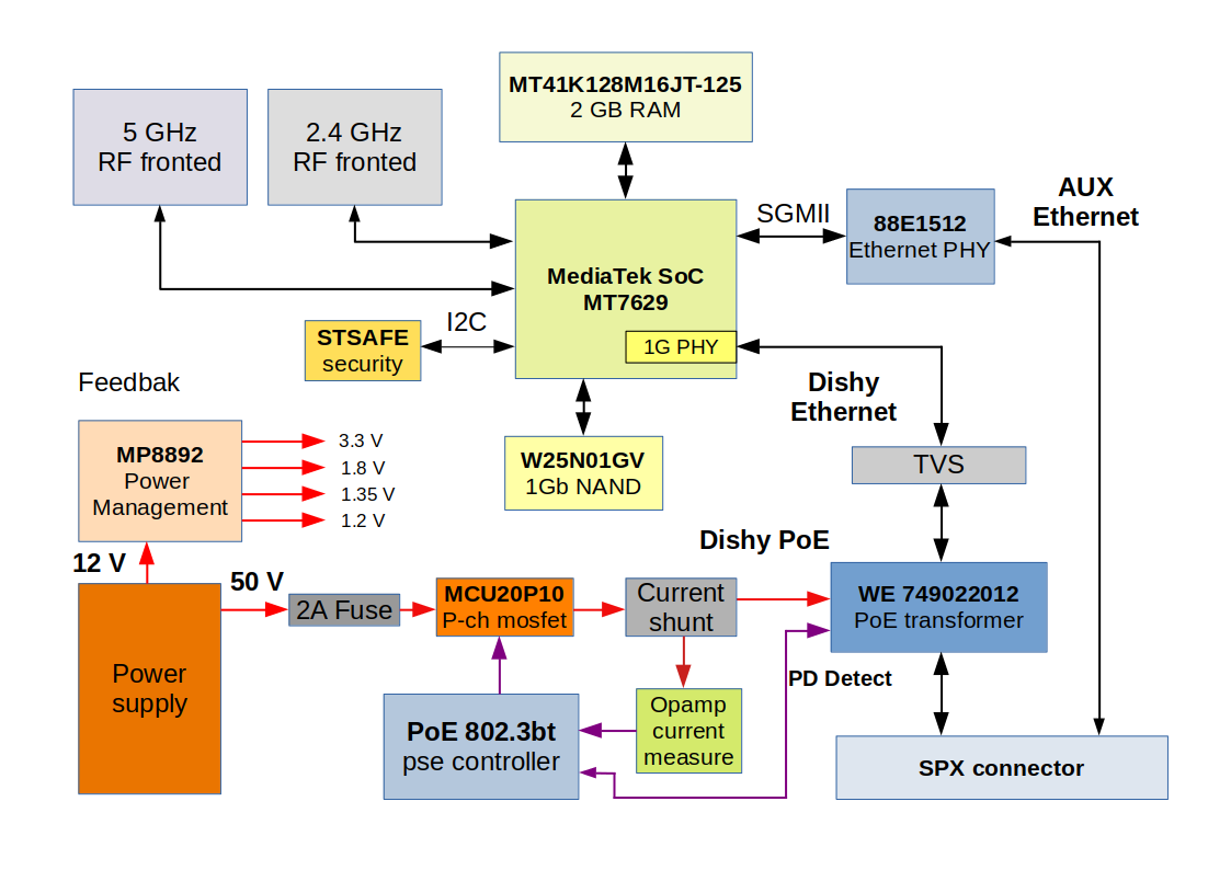
Router block diagram
There might be some inaccuracies, but overall it looks like this.
Firmware
The new firmware is based on LEDE (OpenWrt) 17.01 and MediaTek SDK. SpaceX team claimed that they are trying to remain as close as possible to upstream OpenWrt.
GitHub repository contains almost everything except for proprietary MediaTek drivers and some tools. Also, some of the SpaceX code remains closed, but binaries are there.
Also, this time we have Docker and some additional scripts. Thanks 🙂
But this doesn’t help to build the repository. Some OpenWrt files are missing. Plus, there is a problem with the bootloader signature.
Starlink router uses secure boot, so a certificate is required to build with bootloader binaries. Of course, there is no SpaceX certificate in the repository. But the build system expects this file. This breaks the build process.
I decided to introduce an additional flag, BUILD_BOOTLOADERS, to solve this issue. This flag disables the compilation of the bootloaders.
Both issues are solved in my commits here and there.
System boots from the single NAND chip. The first stage bootloader is burned inside the SoC ROM.
The NAND contains a second-stage bootloader, u-boot, two copies of the Linux kernel, and two operating system copies. Plus a few additional partitions.
Flash layout:
| Partition name | Start offset | Length |
|---|---|---|
| BL2 | 0x00000 | 0x0080000 |
| InactiveFIP | 0x80000 | 0x0200000 |
| ActiveFIP | 0x280000 | 0x0200000 |
| Config | 0x480000 | 0x0080000 |
| Factory | 0x500000 | 0x0200000 |
| InactiveKernel | 0x2000000 | 0x2000000 |
| ActiveKernel | 0x4000000 | 0x2000000 |
| Storage | 0x6000000 | 0x1800000 |
BL2 it’s the second-stage bootloader that starts with the SoC ROM.
This bootloader performs initialization of the hardware: CPU, Memory, and security.
The next stage is u-boot in the FIP container. BL2 selects one of the FIP instances from InactiveFIP or ActiveFIP. The logic is described above in the STSAFE chapter. At this stage, BL2 verifies the signature of the FIP image. Invalid or unsigned FIP images are not booted.
U-boot performs vendor-specific initialization and routines like recovery and booting of the operating system.
Partitions InactiveKernel and ActiveKernel contain squashfs images of the OpenWrt operating system. One is booting, and the second is a backup of the previous version. Perhaps these partition names were derived from the MediaTek SDK.
The Storage partition contains a UBI image with two UBIFS partitions.
| Partition name | Filesystem | Size |
|---|---|---|
| config | UBIFS | 2 MiB |
| log | UBIFS | 2 MiB |
Here is the UBI configuration file. Both partitions are mounted at runtime as rw.
The system starts as a regular OpenWrt system.
SpaceX-specific tasks are defined at the end of etc/init.d/boot
First, a reverse filter is disabled:
# OpenWrt defaults leaves reverse path filters disabled by default, which
# allows LAN clients to spoof WAN addresses and vice versa. Enable on all
# interfaces for security and sanity.
for interface in /proc/sys/net/ipv4/conf/*/rp_filter; do
    echo 1 > ${interface}
done
The next step applies tons of firewall filters.
In the last stage, configures the Marvell Ethernet PHY.
Also, we have a new cool login banner:
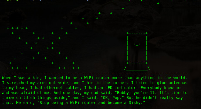
And even a special version for Ukraine. Thanks, SpaceX, for the support!
wifi_control
As in the previous router, all the router operation is controlled by the proprietary wifi_control daemon written in the Go language.
Driver WiFi configuration is stored in plain text format. The file format is typical for the MediaTek platform.
I’m not sure that wifi_control binary configuration is used this time, but probably yes.
Is it possible to run the new wifi_control on the Raspberry PI with the “old” STSAFE chip? Sure!
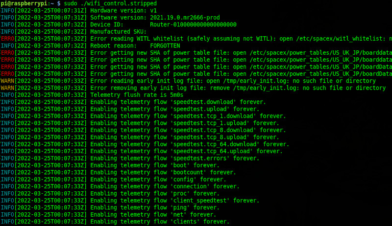
wifi_control properly detects the first-gen platform and tries to configure the IPQ401x system.
(Look at the Reboot reason 🙂 )
Interestingly, the whole router operation is controlled by a single file /tmp/enable_bypass_mode
When this file is present, the router switches to the bypass mode: wifi_control is not running at all, and firewall rules are cleared except for outbound traffic.
Also, the wifi_control daemon runs a built-in web server. This webserver is implemented on the “HTML template” standard Go library.
Here are all the HTML templates files. JS code and CSS are in the neighborhood directory.
All these files are placed into the OpenWrt squashfs path /etc/www/templates/. We can find a lot of interesting there.
For example, the router configuration page. It looks like a factory/maintenance mode page that is not available for regular users:
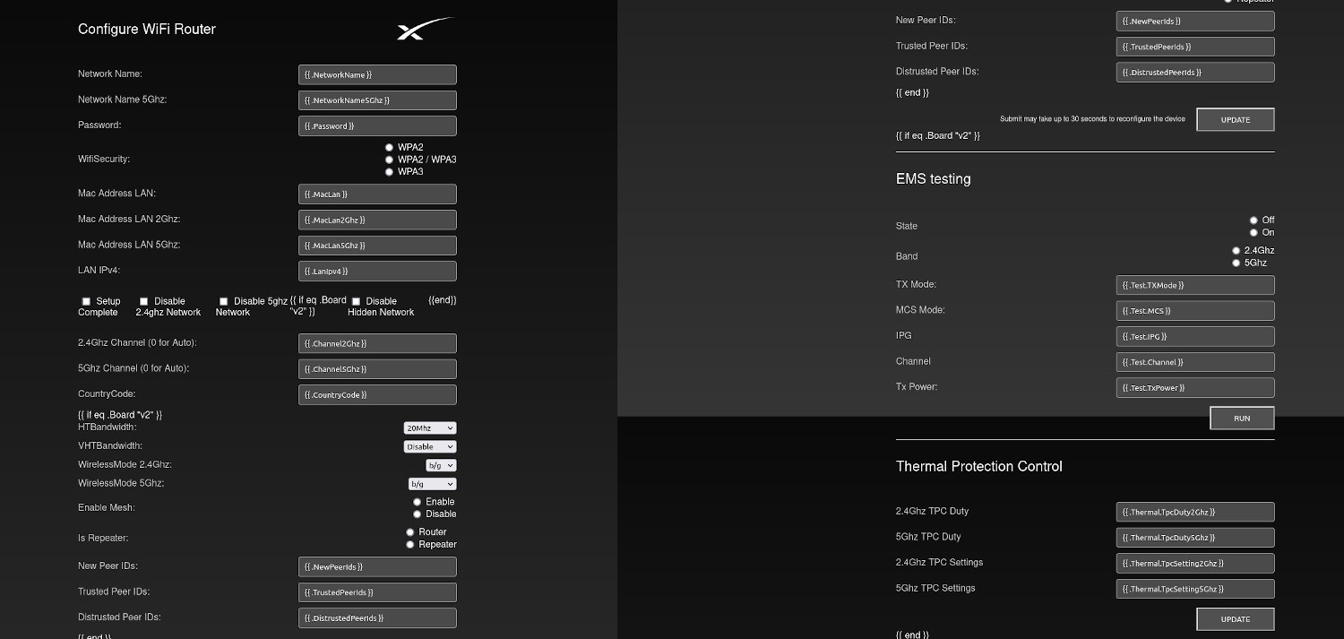
You can see Go templates instead of real data.
But the most interesting it’s a mesh topology page.
It looks like SpaceX is implementing WiFi mesh technology. This means that they gonna separately sell routers or their variants.
I guess it’s not a big secret anymore, plus everything is in the open repository. That’s why I’m writing about this.
It looks like the whole page is just a Work In Progress. Sure, this page displays nothing if opened in the browser.
We need to provide data to see something.
I analyzed the JS code and found that the page expects JSON in a specific format to display IEEE 1905 topology.
The primary data source is topoJSON object in topology-merger.js
Let’s add some random data:
const topoJSON = [
{
"topology information":
    [
        {
            'Device role': 1,
            'AL MAC': "58:d5:6e:3e:05:f7",
            'Distance from controller': 0,
            'Upstream 1905 device': "58:d5:6e:3e:05:f7",
            'Radio Info':
                    [
                        {
                            'channel': 142,
                            'BSSINFO':
                                [
                                    {
                                    'SSID': "Starlink Mesh Client 1",
                                    'connected sta info': [{ 'STA MAC address': "58:d5:6e:3e:05:f7" }]

                                    }
                                ]
                        },
                        {
                            'channel': 147,
                            'BSSINFO':
                                [
                                    {
                                    'SSID': "Starlink Mesh Client 2",
                                    'connected sta info': [{ 'STA MAC address': "58:d5:6e:3e:05:de"}]
                                    }
                                ]
                        }
                    ],
            'Other Clients Info': [ { 'Client Address': "dc:a6:32:02:76:76", 'Medium': "Ethernet" } ],
            'BH Info': []
        },
        {
            'Device role': 2,
            'AL MAC': "32:f5:ee:3e:05:f8",
            'Distance from controller': 4,
            'Upstream 1905 device': "58:d5:6e:3e:05:f7",
            'Radio Info':
                    [
                        {
                            'channel': 16,
                            'BSSINFO': []
                        }
                    ],
            'Other Clients Info': [],
            'BH Info': []
        }
    ]
}
];
And the result:
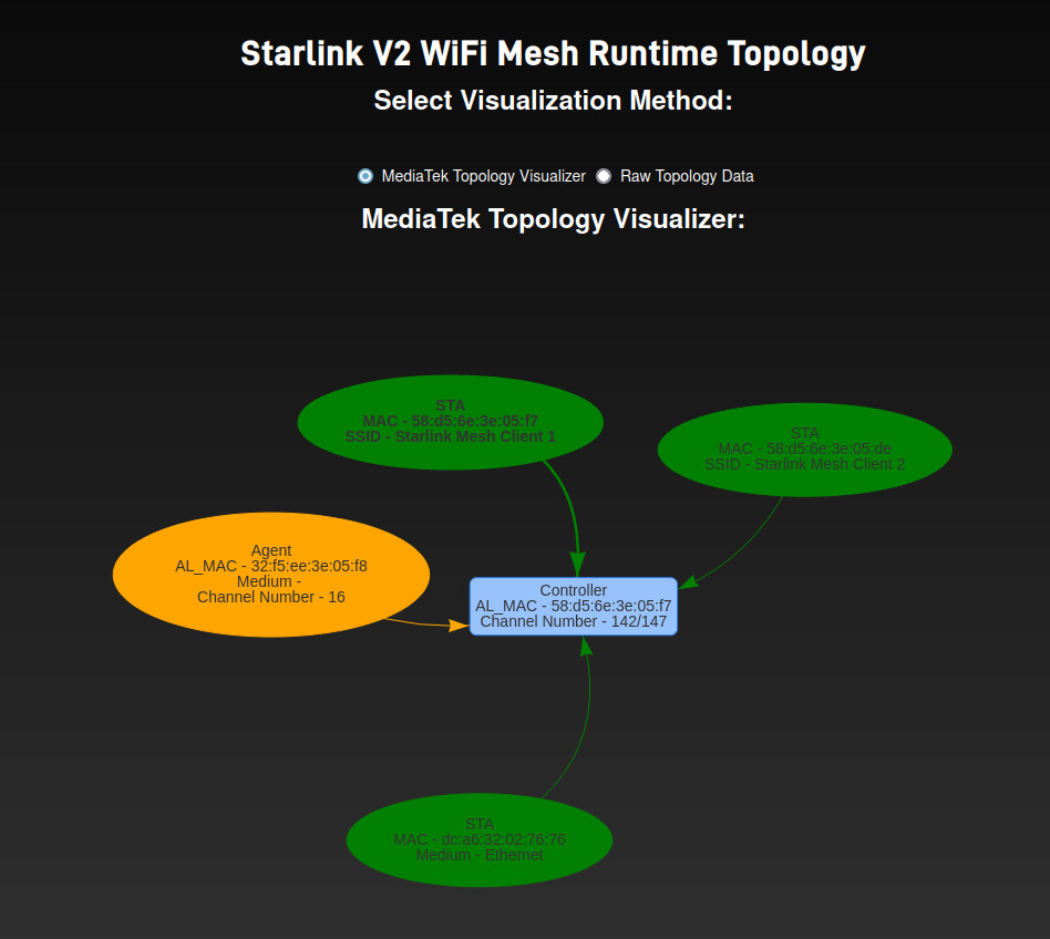
This is a fun page to play. All objects are floating, and it’s possible to drag everything.
Well, I guess that’s all. I hope to write more when I will get the new router.
In the next articles, I will try to answer more questions from the SpaceX repository 😉
Thanks for reading!
If you duplicate and rotate the board 180 degrees, it fits like a puzzle inside the other, thus saving quite a bit of PCB, and hence cost.
Agree
Hello,
Sorry, but I’m a complete layman, self-taught…
How can I change the standard IP of the router management page (192.168.100.1)?
The IP of the router is 192.168.1.1 and it’s OK. I want to change 192.168.100.1
Hello,
Sorry, but it’s impossible. 192.168.100.1 it’s the IP of Starlink Dishy. It’s fixed and can’t be changed.
So to get the average bread eater access to the panel “Configure wifi router” which shows a few photos above is not so easy…?
Yes. It’s just for development or factory process.
Hi, my SL gen 2 is dead, white light indicator on bottom not showing. Can you please show how to repair it?
Thank you.
Hi, it looks like there are 3x RF connectors that could be utilised for external antennas. Do you know what the connector type is?
These connectors are for factory calibration/tests. But you can connect external antennas.
Connector type is MHF-SW23: https://www.i-pex.com/product/mhf-sw23
I got some SW23’s and they didn’t fit those antenna connectors on the board. I’m still trying to identify. Someone said they could possibly be a Murata connector (https://media.digikey.com/pdf/Data%20Sheets/Murata%20PDFs/Microwave_Coaxial_Conn_Cat030E.pdf) but I don’t know which one.
Hey great read! I was wondering, why does switching to bypass mode cause the router to add that ip tables rule
# If bypass mode is enabled, drop all outbound traffic

    ipt -P OUTPUT DROP
What exactly does this mean? Does the router forward L2 or something?
Hello, I would like to know how I can power the router only by injecting 12v voltage, my intention is to connect the entire circuit only to the car’s 12v without needing a 48v inverter, is there any way?
Does anyone have an Idea whats the max Voltage of 50V could I supply it directly by a 16S Lifepo4 55,2V max. ?
Starlink tolerates up to 70V
I saw another person wired their gen 2 router to use 12v and an up converter for the 48v to the dish so that they can use 220v or 12v (on reddit). If this hack was done and the router had an rj45 mod (yours) with the non PoE 12v mod done to the dish, would it be in theory all 12v?
Yes. But I would recommend to use any other router because any other router is better than SpaceX one.
Un Router Xiomi AX 1800 puesto en Bypass es mejor gestionando los datos y velocidades wifi y ethernet que el Router Starlink normal?
Mate, that is an impressive investigation…….Many, Many of these Gen2 units get popped by power, i.e. no white light underneath…..
Do you know which component is usually the culprit ? is that a black fuse next to the AC input ? surely that will pop in bad power situation yeh ?
Yeah, typically (80% of the cases) it’s a fuse and MOV.
You can replace the MOV with 10n471k.
How directional is the Gen2 Router WiFi RF? Could you guess antenna patterns for 2.4 GHz and 5 GHz? Or just to simplify this question, suppose the router’s front directly faces my gear. What dB power loss might my gear see if I rotate the router 90 degrees or 180 degrees? Any guesses would be appreciated, thank you.
It’s mostly perfectly omnidirectional with some predominance in the direction perpendicular to the PCB.
Multi-band inverted-F antenna on each side, a patch antenna in the middle, from your pic of the RF section; “mostly” omnidirectional within a few dB, I guess.
https://en.wikipedia.org/wiki/Inverted-F_antenna#Multi-band_antennas
https://en.wikipedia.org/wiki/Patch_antenna
Online comments I found say the gen2 router is crap. Many say gen3 is crap. They all recommend setting Starlink routers in bypass mode favoring off-the-shelf WiFi routers. Even using the gen2 by itself, comments report reliability and speed gains from using two separate SSIDs, one for 2.4 GHz and one for 5 GHz.
Thank you, this website is one beautiful resource.
Hello, the 8-pin connector of my 2nd generation router has come out of place and the pins under the board have come off. I looked under a microscope and couldn’t figure out the path to jumper. Is there a solution with a picture? Please help. I’m from Iran and there is no spare router here to get. We secretly use Starlink. Please help.
Routing and positioning issues in the Starlink Mini device
I want to inspect the device via TX and RX, but I could not find these pins on the board.
Please, I would like pictures that show their location.
Sorry, I can’t understand your question. What do you mean?
Routing and Positioning Issues in the Starlink Mini Device
I am experiencing routing and positioning issues with the Starlink Mini device.
I would like to inspect the device using the TX / RX (UART) interface; however, I was unable to locate the TX and RX pins on the circuit board.
I would appreciate it if you could provide pictures or diagrams showing the exact location of these pins on the board, if available.
Thank you for your support.
UART is completely disabled on all Starlink terminals since August 2021.
What about SWD pads?
Good post! I have few questions.
You said you successfully build the firmware using docker from github repo.
I’ve seen the repo of your github repo(Space Exploration), and tried to build the firmware, but i failed.
The error comes from build_openwrt.sh, and it said that there is no kernel configuration file.
I’m trying to build the firmware in Ubuntu 22.04.
My question is, did you resolve this kind of problem when you build openwrt image?