 A few months ago, I found a quite unusual satellite antenna on the well-known Chinese portal. The antenna was relatively small, completely flat, and declared as a Ku-band satellite TV antenna. I was really wondered what’s inside and how it works so I decided to buy one sample.
In a few weeks, I got a shabby box containing an actual antenna and a fancy metal stand that can help point the antenna to satellites.
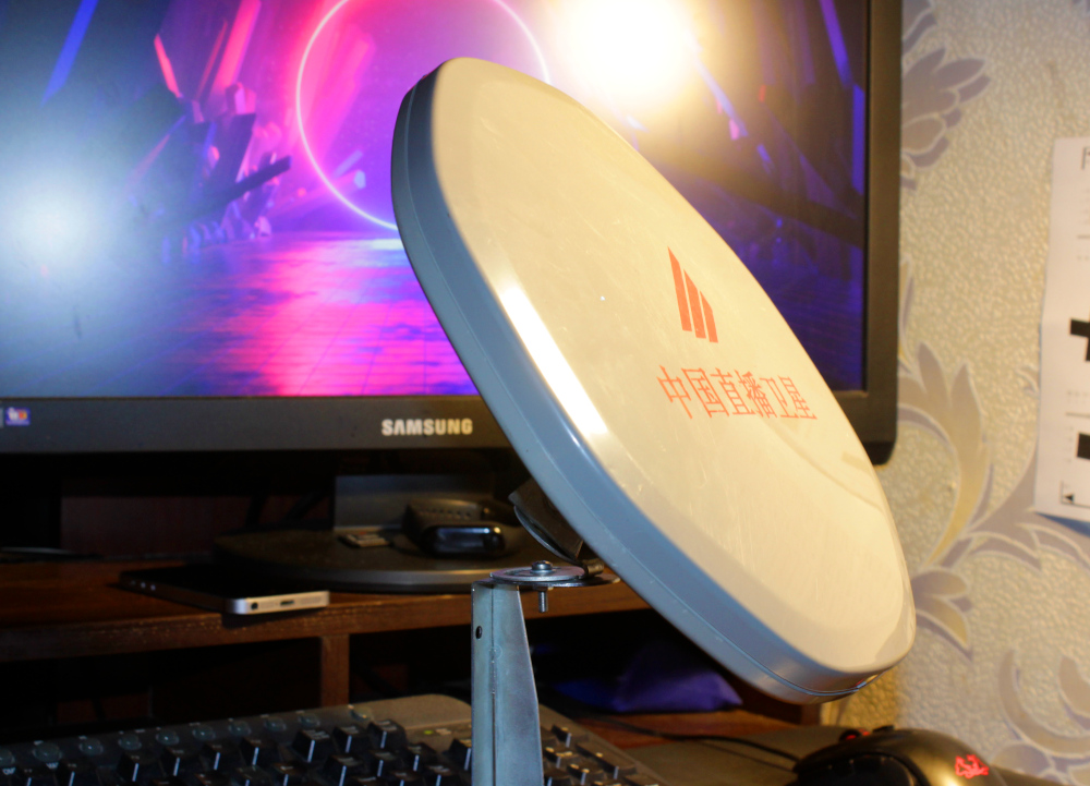
The antenna diameter is 28cm and weighs something around 400 grams (without the stand). Plastic is quite tough and durable.
Here are declared specs for this antenna:
| Frequency band | 11.7 GHz - 12.2 GHz |
| Gain | 60 dB |
| LO frequency | 10750 MHz +- 2 MHz |
| Noise | < 1.3 dB |
| Polarization | Circular LEFT |
| Current consumption | 100 mA |
Of course, I’m not sure that Gain, Noise, and LO stability are real numbers.
The top cover was held with few screws, so it was straightforward to open the antenna. I expected everything.
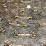
As I mentioned before, a single spiral antenna is not effective on such high bands. You really need a lot of individual antennas and some summation device to collect enough signal energy.
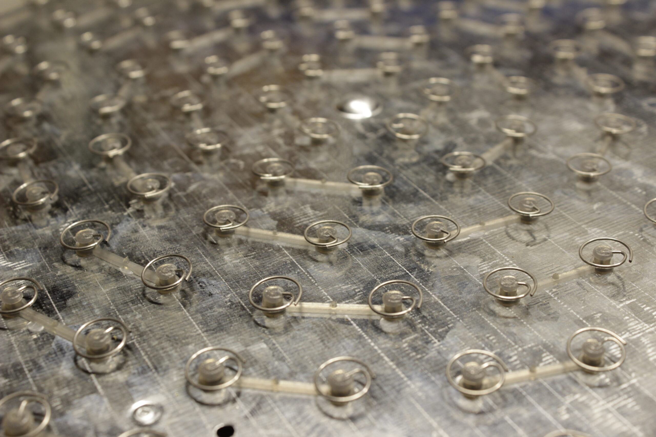
Every two elements are connected with a plastic bridge. Not sure why. It looks like this just a holder (which is definitely required to isolate the antenna element from the reflector cover), but there is probably some hidden meaning.
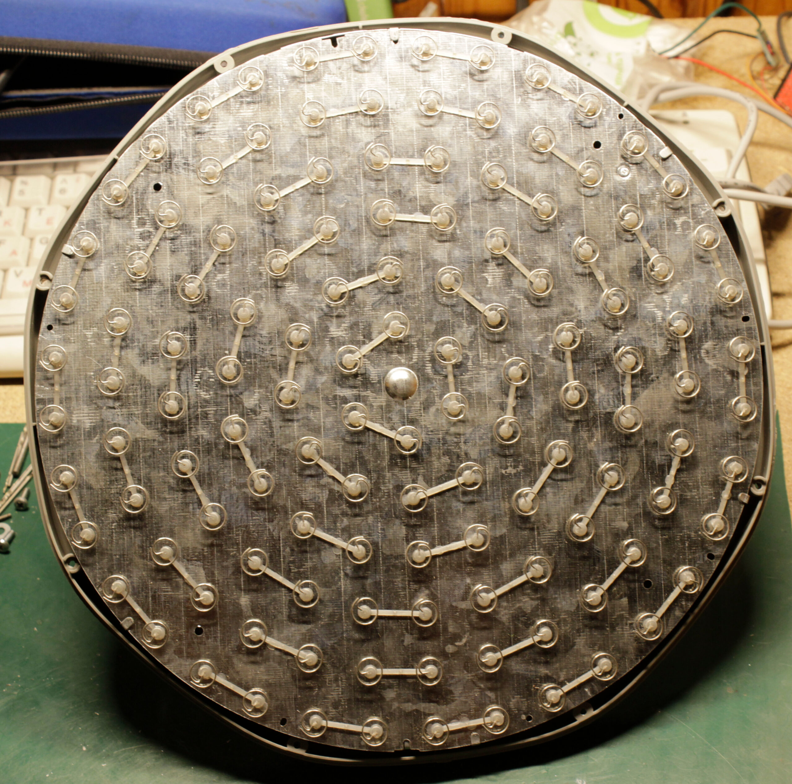
Now the most interesting part.
Under the reflector cover, I found just a big resonator box. Every spiral antenna is represented as a simple probe.
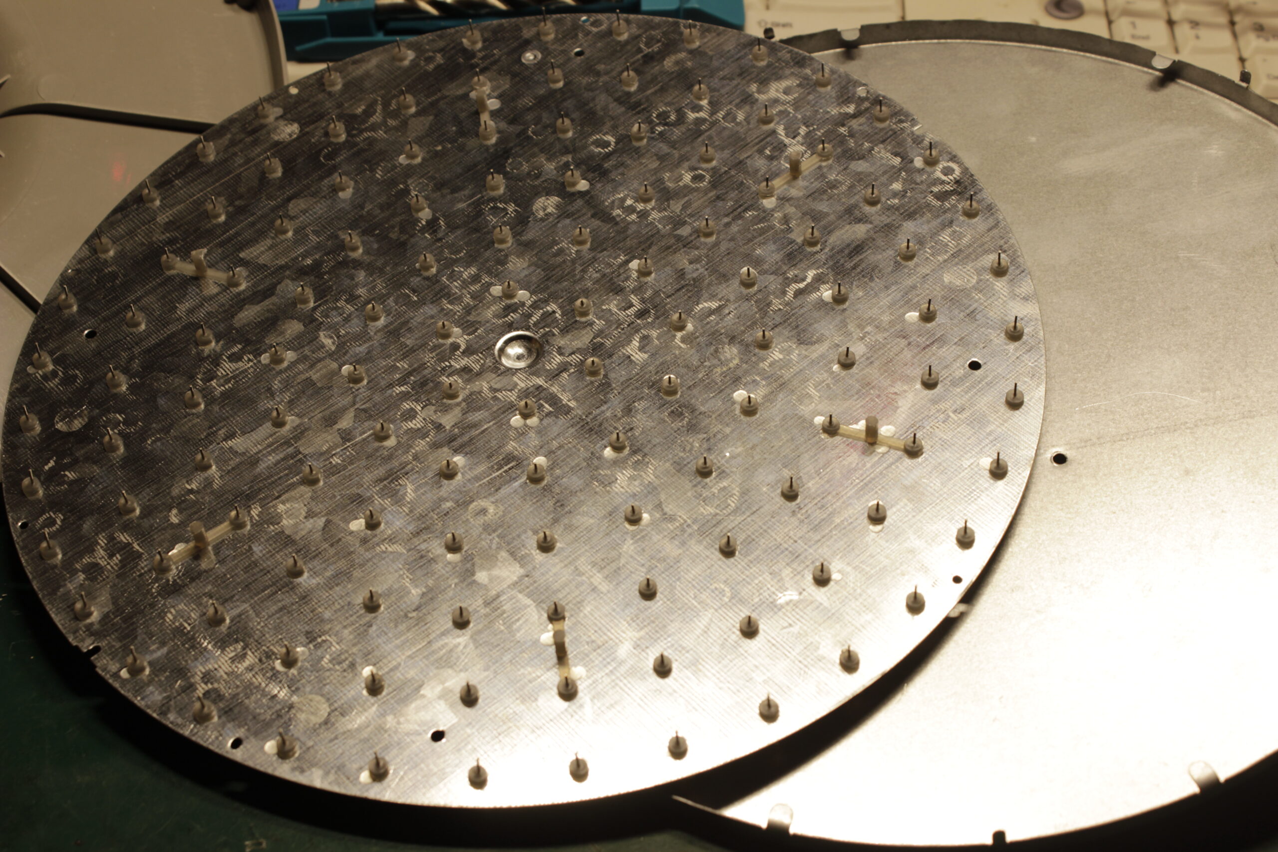
There are also a few plastic bridges, but they definitely keep the distance between the cover and the resonator bottom.
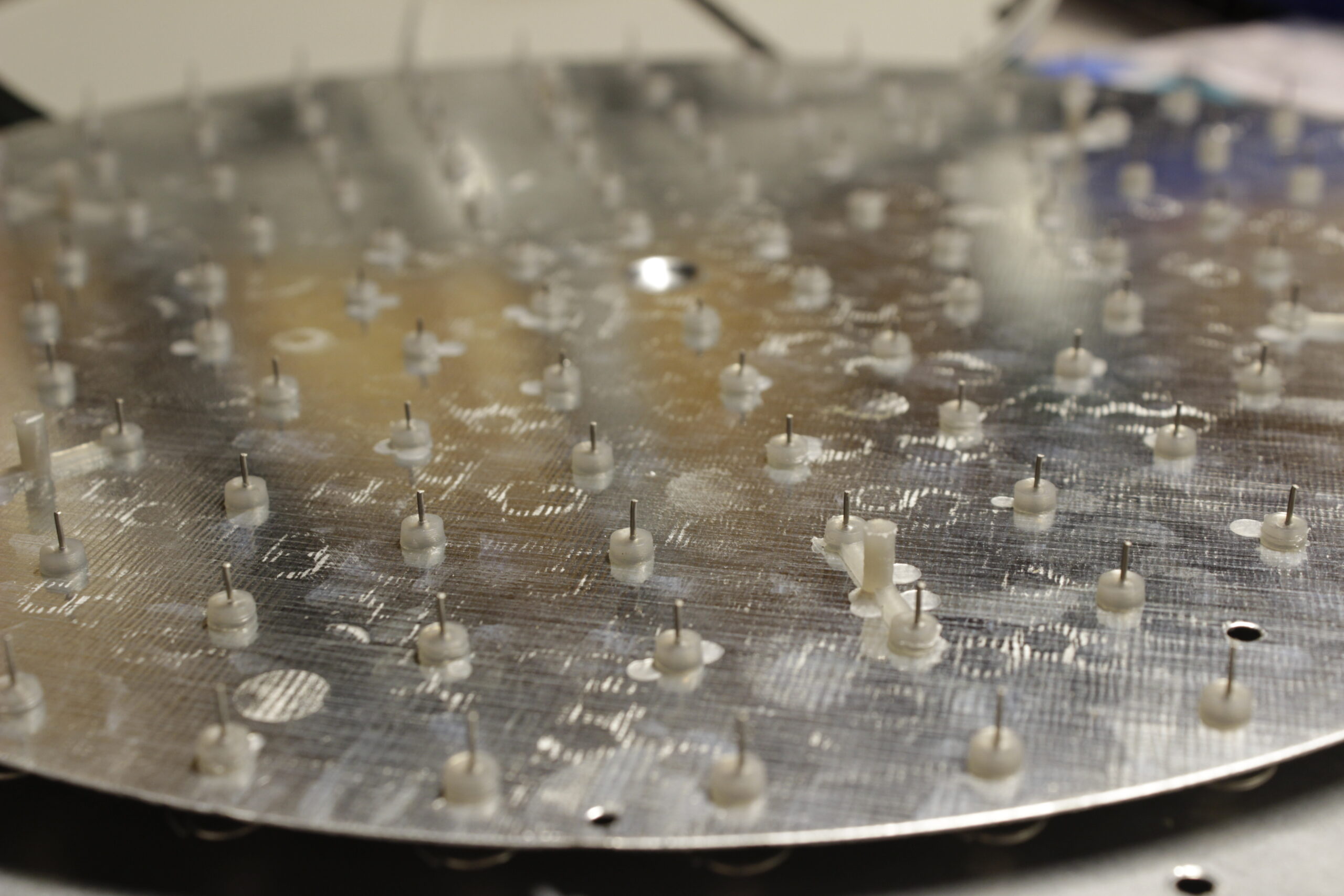
I must note that the whole build quality is not impressive. Most of the probes are not touching the backplate, but some are touching. It looks wrong.
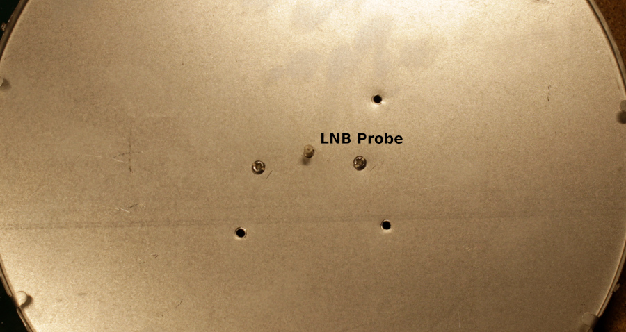
In the center of the resonator box just an LNB probe.
It looks like the antenna schematic is something like this:
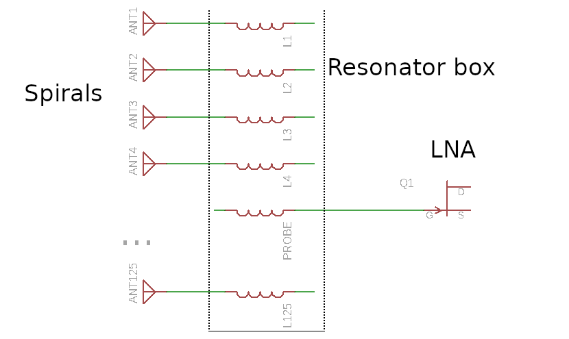 There is probably some parasitic (or not?) capacitance between the probes and the resonator housing.
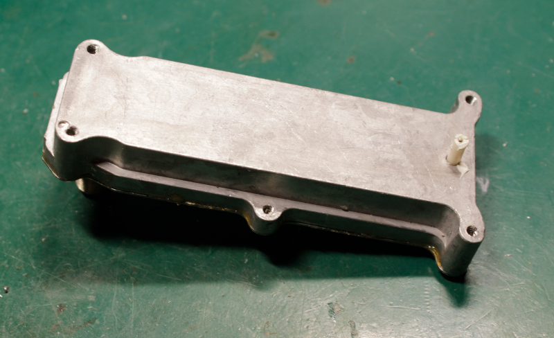
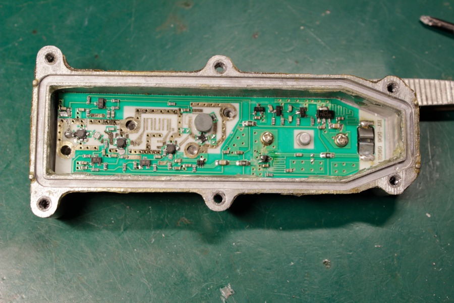
And this is an LNB mounted on the backside of the resonator box.
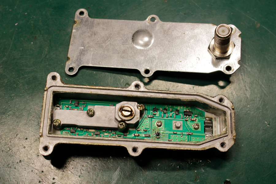
The Schematic is quite simple. Of course, there are no polarization/LO selection circuits.
Testing
Unfortunately, I couldn’t receive anything on this antenna. Pointed directly to the strong Left polarized transponder and nothing. Just a 2-3 dB of signal rise. Of course, this signal can’t be demodulated.
Probably it’s something wrong with my sample (bad LNB), or this antenna requires a much stronger satellite. I don’t know.
It was a fun discovery, but I really don’t wanna buy another sample 🙂
As usual, thanks for reading. Please, post your thoughts down below.
Ah. I was expecting a complex branching power combiner. I guess just doing it in a resonant cavity makes a lot of sense. Neat!
Interesting post. These fat antenna in the picture was designed for the ZhongXing-9A Direct-To-Home Satellite. if you look the paper 327940475 A Circularly Polarized Circular Antenna Array for Satellite TV Reception, can find a more details of the design. Other more general article but in chinese it is in edatop(dot)com/antenna/80675(dot)html . I Hope it be useful.
Thank you.
Thanks for your effort to explain this antenne working.I have just bought one to give it a shot and hope that yours was just a unluck one from the factory as it will my luck maybe as well.
I have use a oplong shape flat panel 30x 40 cm and found this difficult to set up year ago ,but will give this a go and see if I get this working on our Optus D 1 above new zealand ,
Kind Regards Rolf Comez
Lowland Video production
Hamilton New Zealand
Has anyone gotten these to work?
If you have the dimensions (radius , probes length , overall diameter , cavity height , distance between probes) I could run it through CST…
I sent this antenna to the EEVBLOG YouTube channel a few years ago…