 Yagi–Uda antenna is a directional and pretty effective antenna consisting of multiple parallel elements in a line, usually half-wave dipoles made of metal rods.
The Best-known use of this type of antenna is as rooftop terrestrial television antennas, but it is also used for point-to-point fixed communication links and long-distance shortwave communication by shortwave broadcasting stations and radio amateurs.
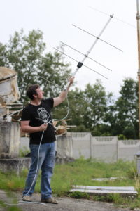
This article will show how to build a simple 5 element antenna for 144 MHz bands from widely available parts and how to get some fun with it.
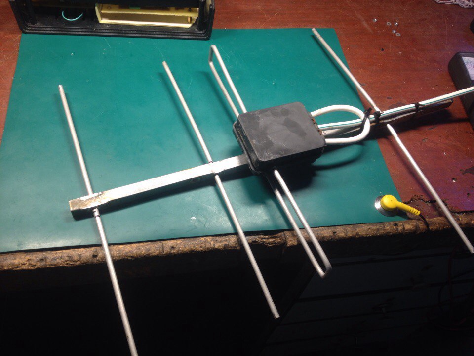
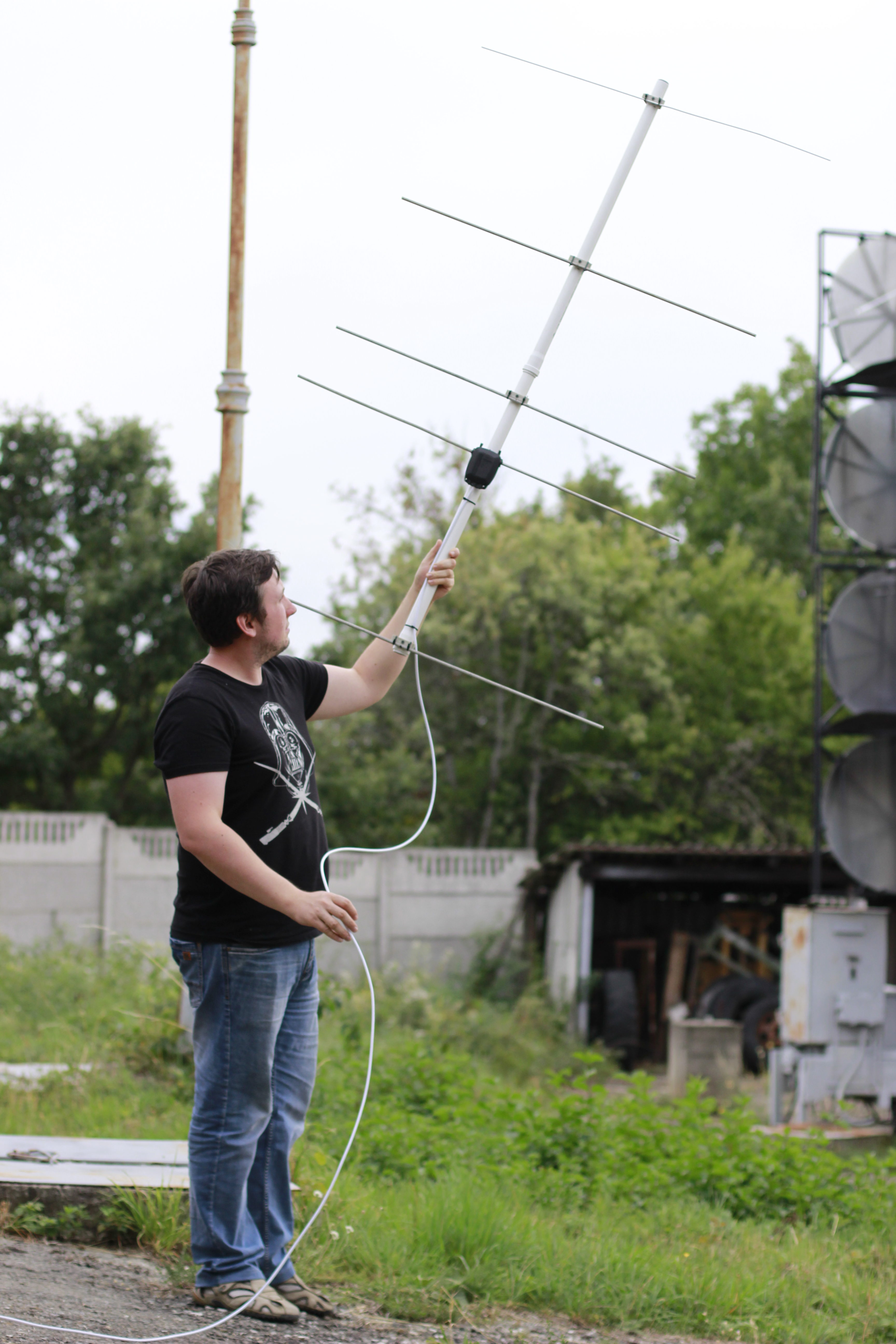
This is my antenna.
You can see that everything you need to build such an antenna is two plastic water pipes, a few aluminum rods, plastic ties, and a 75-ohm tv cable.
But before actual building, we should discuss some theories and calculations of this type of antenna.
Every Yagi antenna contains a reflector, an active (or driven) element, and at least one director. The number of directors can be even 15. Increasing the number of these elements increases total antenna gain and directivity, but this requires precise tuning (element sizes and distances between them).
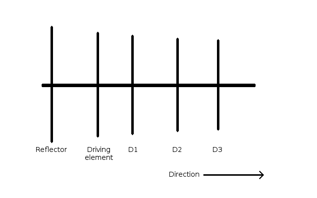
5 element antenna contains 3 directors, and this is a good balance between complexity and performance.
Calculations are straightforward.
Lengths of the elements:
Reflector = 0.495 * wavelength
D1 = 0.440 * wavelength
D2 = 0.435 * wavelength
D3 = 0.430 * wavelength
Where wavelength = c/f, f – antenna central frequency in Hz, and c – the speed of light.
Our selected band is 144 MHz or 144000000 Hz, speed of light – 300000000 meters per second.
Wavelength = 300000000/144000000 = 2.083 or simple – 2 meters.
So our lengths are:
Reflector = 0.495 * 2 = 0.99 meters
D1 = 0.440 * 2 = 0.88 meters
D2 = 0.435 * 2 = 0.87 meters
D3 = 0.430 * 2 = 0.86 meters
And distances between elements:
Reflector – Driven element = 0.125 * wavelength = 0.125 * 2 = 0.25 meters
Driven element – D1 = 0.125 * wavelength = 0.25 meters
D1 – D2 = 0.250 * wavelength = 0.250 * 2 = 0.5 meters
D2 – D3 = 0.250 * wavelength = 0.5 meters
But what about a Driving element? How to calculate it?
There are two big types of these elements:
- 1/2 wave open dipole
- folded dipole
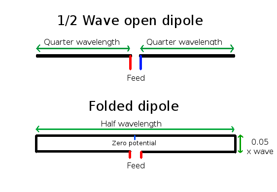 So for the open dipole length of both parts is: 2.083 * 0.25 = 0.52075 meters
Folded dipole length: 2.083 * 0.5 = 1.0415 meters
Height: 2.083 * 0.05 = 0.10415 meters
The typical distance between feed connection points is 1-3 cm, depends on your boom diameter.
Both dipoles are symmetrical types of antennas.
The main difference between these two types is wave impedance.
An open-type dipole has impedance near 70 ohm
Folded impedance is near 300 ohms.
The typical impedance of TV coaxial cables and home receivers is 75 ohm
The cable and antenna impedance should be carefully matched, or you will get a big loss of power.
It also is very important to transform the symmetrical antenna line to the non-symmetrical coaxial cable.
For the folded dipole, a simple way to do this is a U-knee, made from the same 75-ohm cable. U-knee acts both like symmetry and impedance matching device.
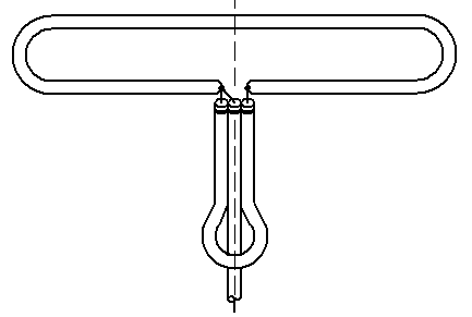
The length of this additional cable is ~0.4 of wavelength.
In the picture below, you can see another antenna for the 433 MHz band with such U-knee.
In the current 144 MHz project, the open-type dipole is used due to its simplicity and material saving.
All you need is to transform the line from symmetrical to non-symmetrical without impedance matching for such type dipoles. A good solution may be a special transformer.
I’m using a transformer from the cheap TV antenna amplifier in my antenna, like in the photo below.
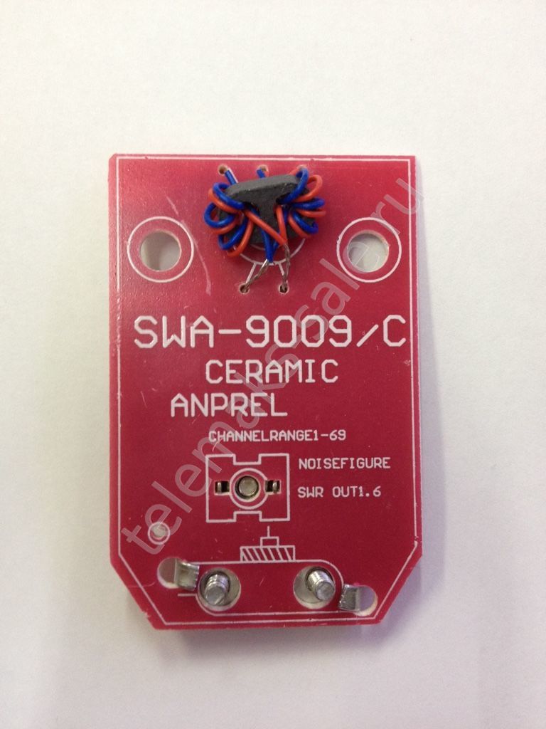
The bottom part with the amplifier itself was cut.
 Of course, you can create such transformers if you have a proper ferrite.
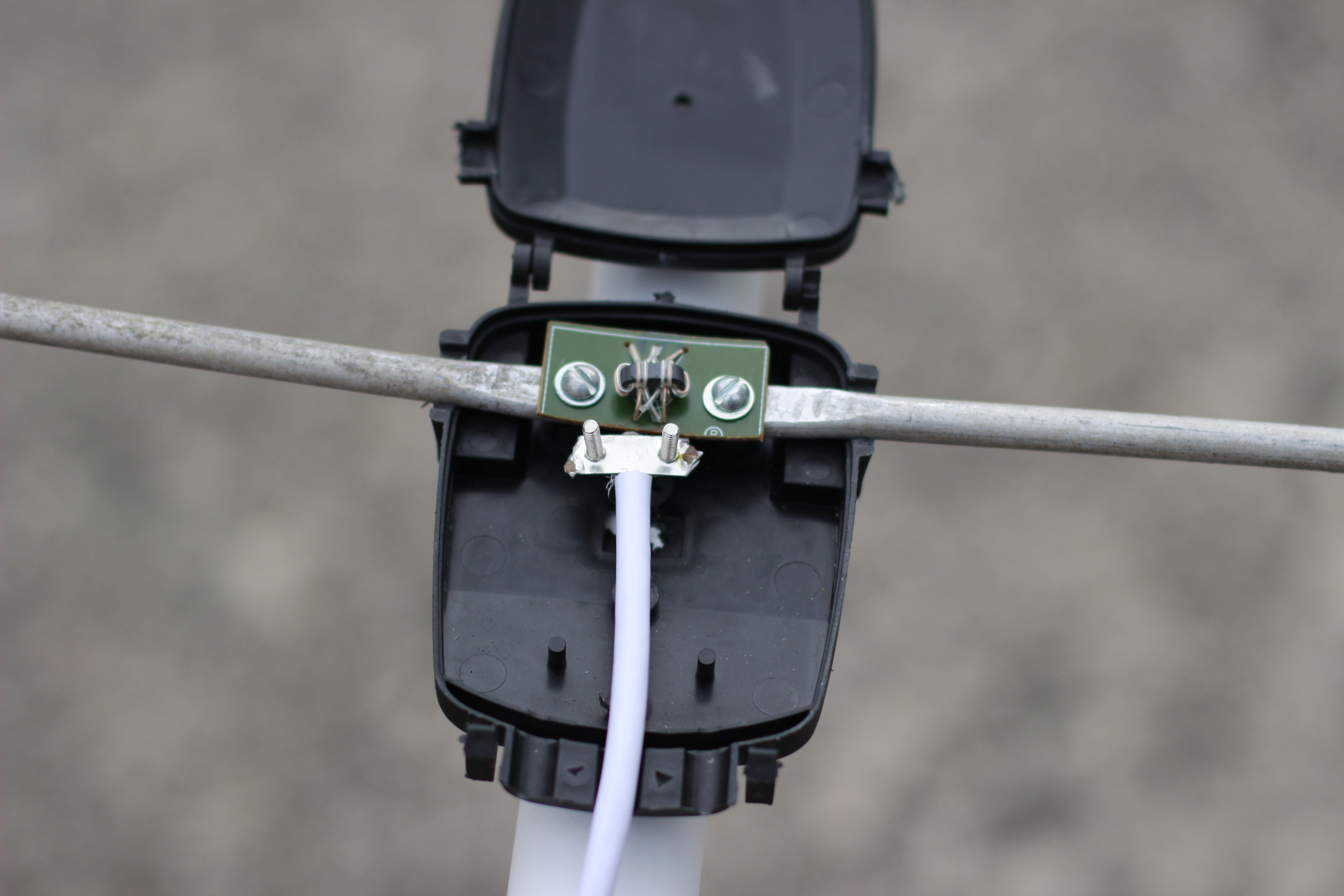
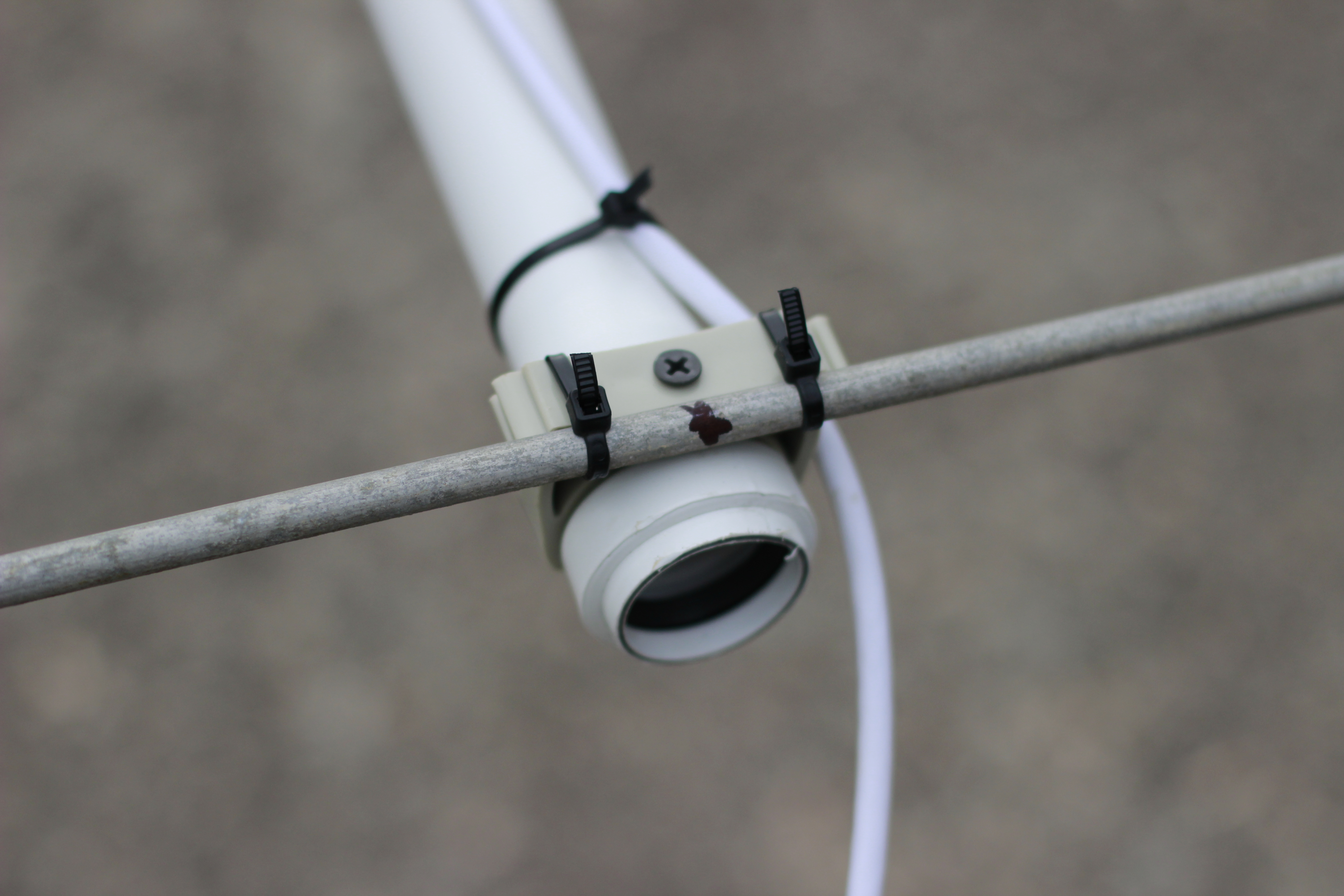
To fasten the rod, you can use plastic ties and wall fasteners for your boom diameter.
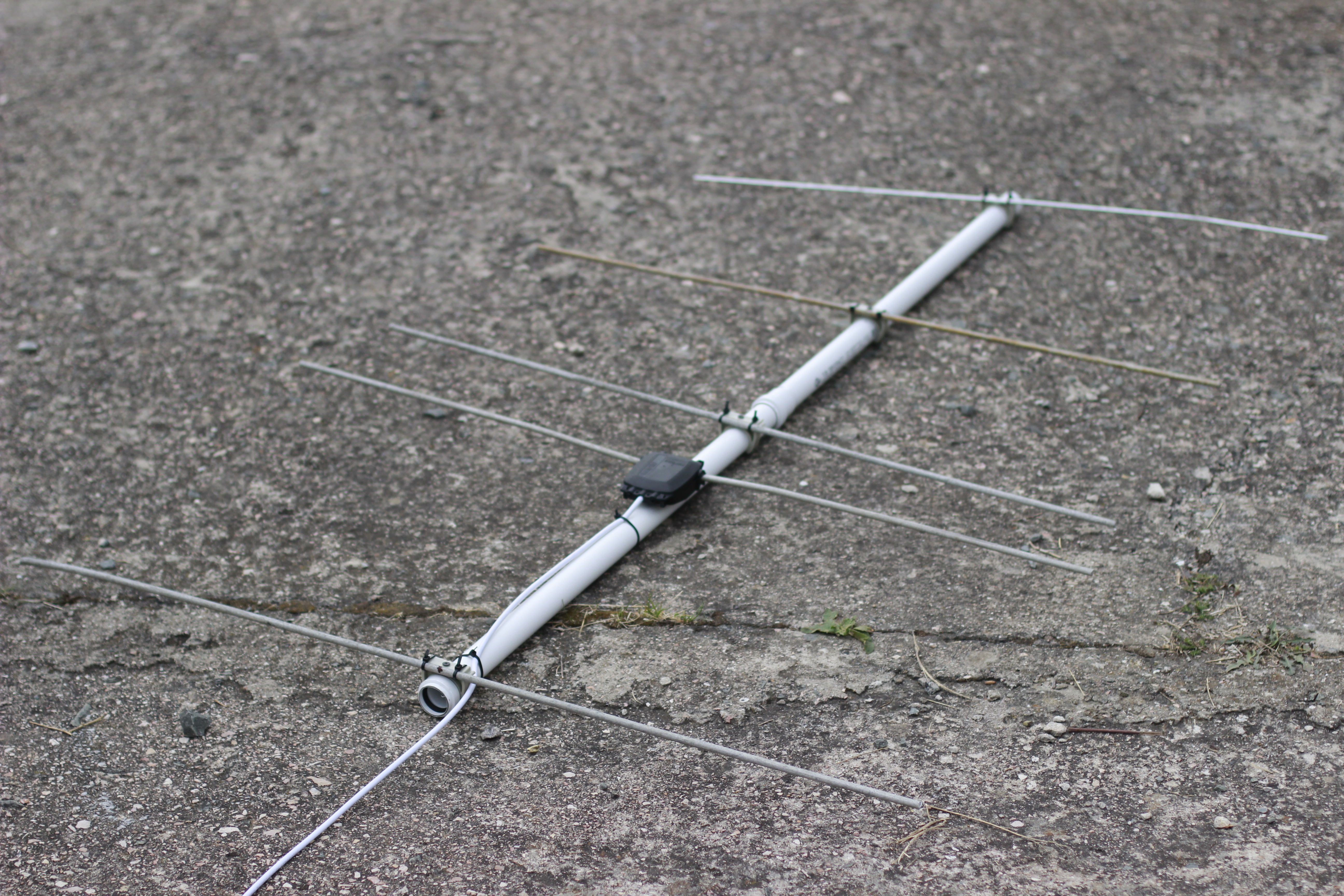
 Finished antenna
Using formulas in this article, you can get a great good antenna for educational uses and non-critical applications.
Of course, in the real world, everything little bit complex.
It would help if you considered with boom and rod diameter, so more precise calculations are required. I’m strongly recommended to use this calculator for such types of antennas.
So, why 144 MHz?
This antenna is quite broadband, so you can really receive signals from the FM band and to the 160 MHz, sure.
Most interesting in this band is:
- FM & TV stations
- Aircraft communications and airports (118 – 135 MHz)
- NOAA weather satellites (137 MHz)
- HAM radio (145 MHz)
- ISS (145.8 MHz)
The next article will show how to receive these signals using a popular RTL SDR receiver.