 The Starlink Mini terminal is designed as a compact, all-in-one solution with an integrated Wi-Fi router. While this design is ideal for typical consumer use, certain applications—such as custom networking setups, embedded installations, or power-constrained environments—may benefit from removing the internal router entirely. In this article, I’ll detail the process of physically removing the built-in Wi-Fi router board from the Starlink Mini, allowing the terminal to operate solely via Ethernet and offering greater flexibility for advanced users.
Please note that this modification applies only to the Starlink Mini 1 (as of June 14, 2025). Hardware changes in future models, such as the expected Mini 2, may render this process invalid.
Starlink Mini teardown
The disassembly process requires patience and accuracy. I recommend using metal spudgers and a plastic prying tool.

Additionally, you will need a thin, flexible knife or a thin metal wire to remove the router’s PCB.
I prepared a video manual about the teardown process.
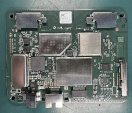
Please note that there is no need to remove the metal plate from the Starlink PCB. You can stop the teardown process after removing the router’s PCB.
Removing the metal plate is strongly discouraged. This plate serves as both a heatsink and an EMI shield.
The Starlink CPU runs hot, and without proper cooling, it may throttle the CPU or antenna array. In addition, the plate is glued around the corners with conductive adhesive to ensure effective electromagnetic shielding. The Starlink Mini PCB generates significant EMI, and SpaceX reportedly faced challenges achieving compliance.
Removing the plate can lead to increased emissions and potential interference with nearby electronics.
Starlink Mini PCB connector
The exact type of the connector is unknown. It might be a custom order. But the pitch of the connector is 2 mm, so any standard 2 mm header will fit here nicely.
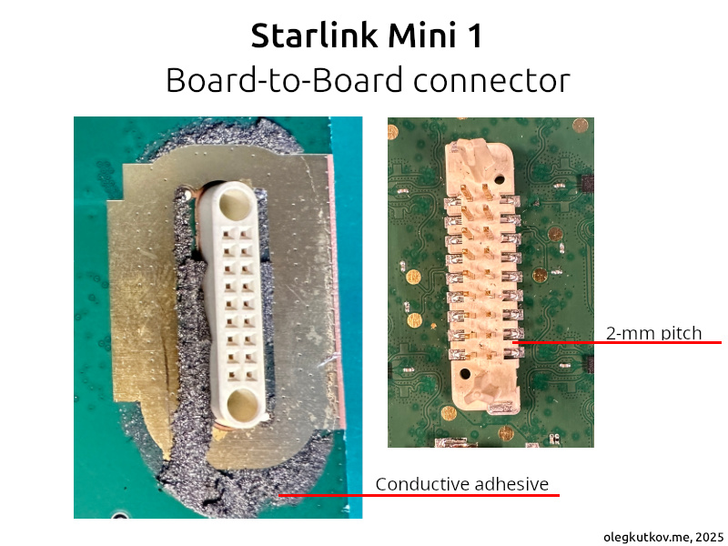
You may notice that this connector is secured with a similar conductive adhesive and a large non-masked grounding area. Additionally, a shield is placed over the connector on the router’s PCB.
This is all done to help contain the EMI.
Connector pinout
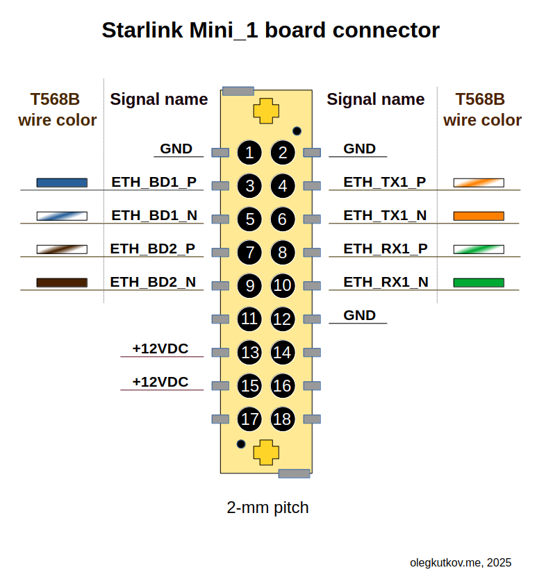
Starlink Mini uses a 1 Gbps Ethernet link between the primary unit and the router. Please note that there is no Ethernet transformer; instead, a direct PHY-to-PHY connection with some decoupling is used. This is acceptable for short distances. With any custom design installation, the Ethernet transformer is mandatory.
The primary voltage bus is 12 VDC.
The connector pinout (Starlink Mini side) is in the image below.
Ethernet line signals are mapped to the corresponding T568B twisted cable colors. Pins 11, 14, 16, 17, and 18 are not used in the current modification and mainly serve Starlink-Router monitoring purposes.
It’s recommended to use all 12 VDC and GND lines.
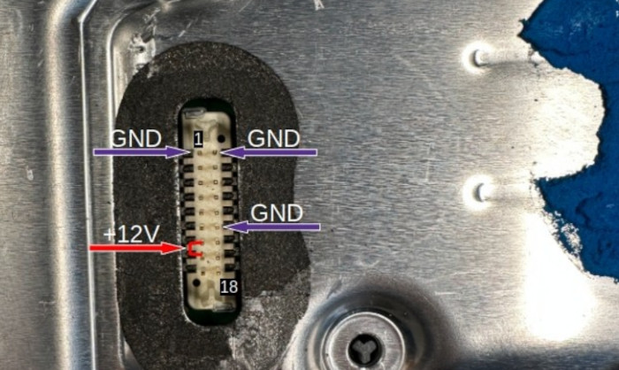
A reference image to help you identify pins:
Direct Ethernet connection
Below, you can see an example schematic of the direct Ethernet connection to the Starlink Mini_1 PCB connector. This schematic provides required Ethernet isolation and minimal power filtering to ensure proper operation.
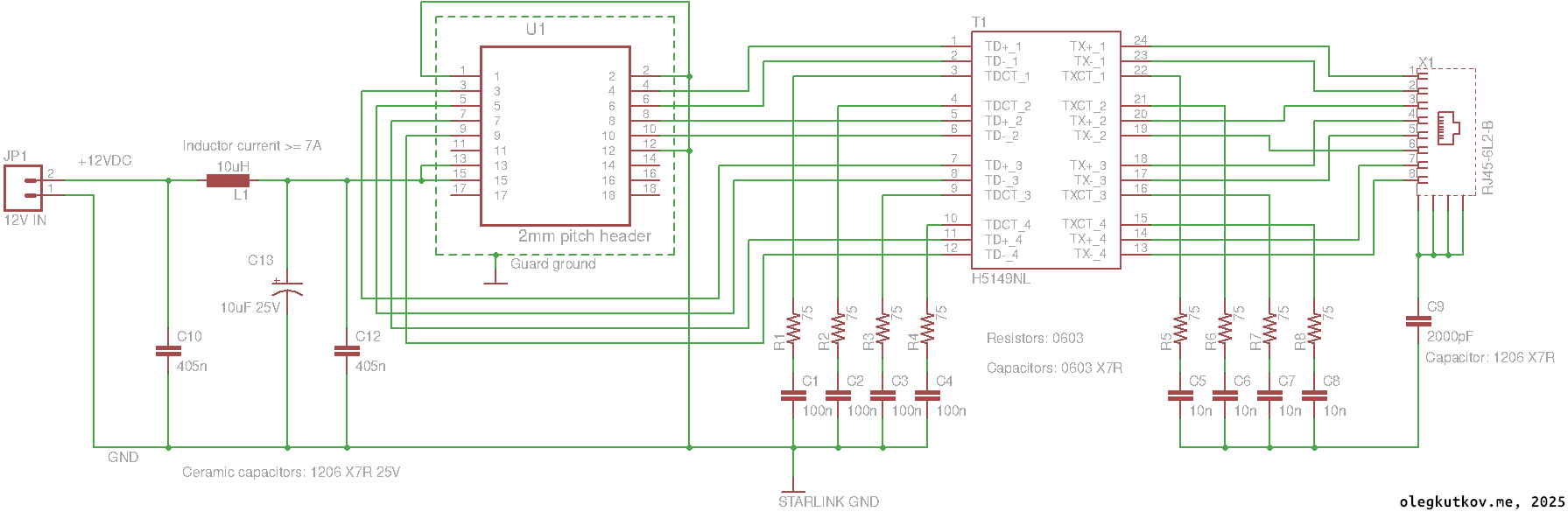
It’s recommended to put a guard ground around the U1 connector. The most optimal design includes conductive adhesive and shielding.
Please, keep wires between the connector and Ethernet transformer as short as possible.
Nominal runtime current over 12V is ~3A with short spikes up to 5A.
Please select the L1 with the appropriate rated current to avoid overheating.
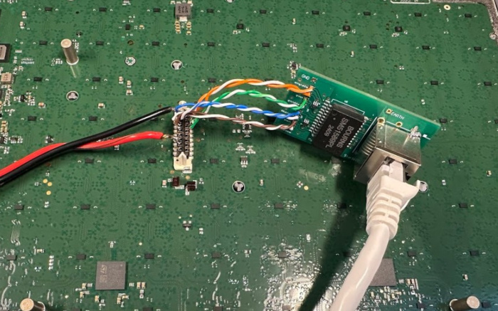
Proof-of-concept using my Ethermod adapter:
Network configuration
The Starlink terminal provides a DHCP IP address in the 192.168.100.0/24 network when not connected to Starlink satellites.
The terminal itself is available at address 192.168.100.1, running a simple web UI and gRPC monitoring/control server.
It’s convenient to get Starlink debug data using grpcurl. Example request (getting the current status of the terminal):
grpcurl -plaintext -d {\"get_status\":{}} 192.168.100.1:9200
SpaceX.API.Device.Device/Handle
After connecting to the Starlink network, the Ethernet interface provides a tunneled DHCP service, assigning clients IP addresses from the Starlink pool – typically a CGNAT IPv4 address (e.g., 100.72.116.102) and a link-global IPv6 address. This network configuration provides access to the Internet.
Please note that the Starlink DHCP server provides only a single IP address. Therefore, you can connect only one host or an upstream router directly to share the connection with multiple devices.
After acquiring the “external” IP address, your client naturally loses access to the 192.168.100.1 host.
To fix this, you can add a static route to the terminal:
sudo ip route add 192.168.100.1 dev ethX
Replace ethX with the name of your Ethernet interface connected to Starlink.
No additional configuration is required. Once your host obtains an IP address after joining the Starlink network, it should have internet access.
Don’t forget to monitor account status and connection state via the gRPC output.
Bonus – important gRPC status codes
The gRPC get_status output contains a lot of helpful information.
In case of connection issues, the “outage” section should appear in the gRPC output. Example:
"outage": {
"cause": "NO_SCHEDULE",
"startTimestampNs": "1815683934050410150",
"durationNs": "4320001119",
"didSwitch": true
},
Possible values of the “cause”:
BOOTING – The terminal is starting up, initializing modules, and waiting for a GPS fix.
THERMAL_SHUTDOWN – The terminal has overheated and shut down to protect components.
NO_SCHEDULE – The terminal is unable to communicate with satellites. This could be due to a weak signal, incorrect GPS data, or other issues.
NO_SATS – The terminal failed to detect any satellites in the sky.
OBSTRUCTED – An obstruction is detected along the radio beam path.
NO_DOWNLINK – The terminal cannot receive data from the satellite.
NO_PINGS – The satellite has lost connection to the ground segment, although the terminal’s connection to the satellite remains intact.
You can monitor the status of your Starlink account in the section “disablementCode“.
Possible disabement codes:
UNKNOWN_STATE – Terminal reported an undefined or unrecognized state.
OKAY – The Account is active and should provide access to the internet.
NO_ACTIVE_ACCOUNT – Starlink account has been removed or the service is on pause.
TOO_FAR_FROM_SERVICE_ADDRESS – The terminal is operating outside the registered service address region.
IN_OCEAN – Terminal is located in an oceanic zone not covered by the current service plan.
BLOCKED_COUNTRY – Terminal is located in a country where Starlink service is not permitted.
DATA_OVERAGE_SANDBOX_POLICY – Data cap exceeded; Change service plan to get more data.
CELL_IS_DISABLED – The local service cell is disabled in the Starlink system.
ROAM_RESTRICTED – Roaming is not allowed under the current account or plan.
UNKNOWN_LOCATION – Terminal location cannot be determined by the Starlink satellite.
ACCOUNT_DISABLED – The Starlink account has been suspended or permanently disabled.
UNSUPPORTED_VERSION – Terminal firmware is incompatible or outdated.
MOVING_TOO_FAST_FOR_POLICY – Terminal is moving too quickly (e.g., in a vehicle or aircraft), violating policy limits.
UNDER_AVIATION_FLYOVER_LIMITS – Terminal is under an aircraft flyover zone where service is restricted.
INVALID_COUNTRY – Terminal is in a country not supported by Starlink.
UNLICENSED_COUNTRY – The terminal is located in a country where Starlink lacks regulatory approval.
The disablement code should always be available after a successful connection to the satellites. The Starlink system provides this information. The user terminal itself has no knowledge of service plans, countries, regional, or velocity restrictions – it simply follows commands received from the Starlink satellite.
Thanks for reading!
amazing Oleg. Can we investigate how to spoof its location to another country to enable the service in countries where its “banned”. Due to stupid corrupt african countries in most of Africa its “banned” would be great to use the reverse engineering here and convince it its somewhere else.
Hello,
I mentioned in my article:
> The user terminal itself has no knowledge of service plans, countries, regional, or velocity restrictions – it simply follows commands received from the Starlink satellite.
The satellite in the sky knows its position and which cell it’s serving. Thus, it always knows where (at least at the Cell level) a given terminal. If the cell is disabled in the Starlink system, it will refuse connections from the ground.
We can’t spoof satellites in orbit.
It’s the same issue I’m having here in Algeria I managed to get it here the Starlink Mini but after turning it on it says Restricted, funny enough other African countries somehow managed to get it running where it’s also not supported. So my question stays here if Starlink bans the usage of Starlink in specific countries if they get contacted or how does it work? For example in Syria it’s banned but people still use it normally everyday. And I think there is somehow a whitelist or maybe in the config it can be set to allow connection? Sadly there is no UART as I know.
WHat a barbarian disassembly, jesus.
Show us your method of disassembly.
Hi, congrats on your work!
Did you check the power consumption without built in WiFi router?
Is it worth to disassemble Starlink Mini, compared to using it with built in router in “bypass mode”?
Hello Mr Kutkov. Thank you for posting this. I have a new starlink mini as of Sept 2025 that I plan to flush mount using velcro on the flat surface to bond it to a skylight in an airplane from the inside. The edges will be partly obscured because the skylight is about 1/2″ narrower than the antenna. I am concerned that the metal at the edges of the skylight will radiate microwaves downward into the cabin and my head. Would covering the upper, obscured edges of the antenna with carbon fiber block any RF emitted by the edges? I realize signal degradation may occur, but if it works, I need to know how to keep from microwaving my brain with reflected microwaves. Thanks, Karl
I love this. Thanks for showing the video and how to teardown. Starlinks are banned on cruise ships and will be confiscated, I’m wondering if the internals would fit inside of a laptop and you can pass off the starlink as a laptop and avoid confiscations and high fees in order to use their wifi.
Can run it with a Ethernet cable found in the Gen 2 + Starlink mini (30v) cable wiring to run it inside my truck cab?
Is there any benefits in removing the router completely as opposed to just disabling the Wi-Fi “bypass mode”?
Hi where i can get a CPU for a Starlink Mini, needed for replacemente anybody??
Hello, you can’t replace the Mini CPU since the CPU is bound the account
https://olegkutkov.me/2025/05/22/how-to-physically-transfer-starlink-account-from-one-terminal-to-another/
Is mean that RIP for that starlink mini, the CPU is in short in the 5v line, because a water damage
Can the gps be disabled to prevent the speed restriction shutdown?
Hi Oleg,
Looking to replicate this with your EtherMod PCB. The original Ethernet socket (RJ45-6L2-B) is obsolete – do you have a part number for the replacement ethernet socket you fitted?
Thanks!
Hey Oleg.
1. I want to measure beam patterns of the mini on Tx and Rx. Any suggestions how to do that? I cannot force it to transmit if not under open sky. Also I don’t know how to follow its pointing.
2. Can the mini work without GPS? or with jammed GPS (other locations)? I have the residential subscription with a fixed location. what are the constrictions?
3. Any hidden WEB GUI other than the basic monitoring at 192.168.100.1?
Thank you
Здравствуйте Олег! Возможно вы знаете как можно восстановить прошивку штатного роутера Starlink mini? После попытки чтения nand flash w25n01gv на программаторе, дамп не прошел верификацию. После этого роутер не загружается, нет WIFI, отсутствует лог при подключении по uart, на кнопку reset не реагирует.
Здравствуйте. Возможно вы как-то повредили чип или прошивку при выпайке или программатором. Тут уже сложно сказать.
Самое простое решение – поставить флешку от другого такого же роутера, разбитого. Там прошивка не привязана к плате, так что должна заработать.