 My 12V mod for the REV3 is extremely popular. Today, I will show you how to make a similar modification with the new terminal REV4 (a.k.a V3).
As always, a lot of pictures below.
The new terminal is quite challenging to disassemble, but it’s possible. Just don’t rush.
All PoE and primary DC-DC step-down circuits in the new terminal are placed on a separate board. This board is fixed on the backplate and connected to the primary board via an unusual 2mm pitch connector.
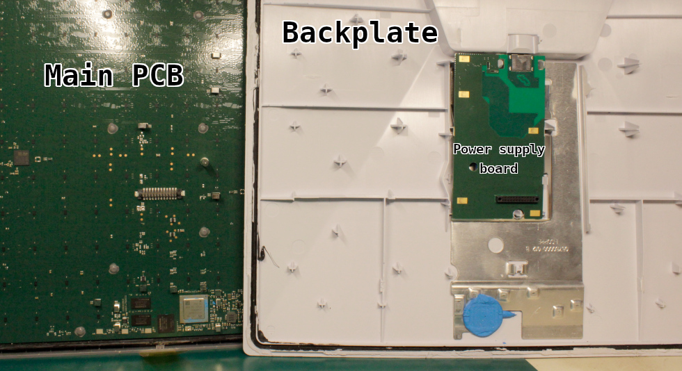
The need for a separate board is likely due to the need to place the connector at the base of the complex back cover. An aluminum plate behind the PS board is a heatsink bot for the PS board and SoC on the primary PCB.
Unfortunately, I couldn’t identify the type of this connector. It’s a standard 2mm pitch header with additional plastic stands for better fixing. It’s possible to use a standard 2mm header like this one.
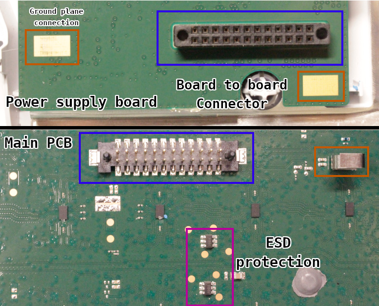
This connector (let’s call it a “system connector”) carries various signals: supply voltage, I2C, and Ethernet.
Additionally, the power supply board ground plane is connected to the primary PCB via spring plates and capacitors in series. This helps to create a short path for the high-frequency currents.
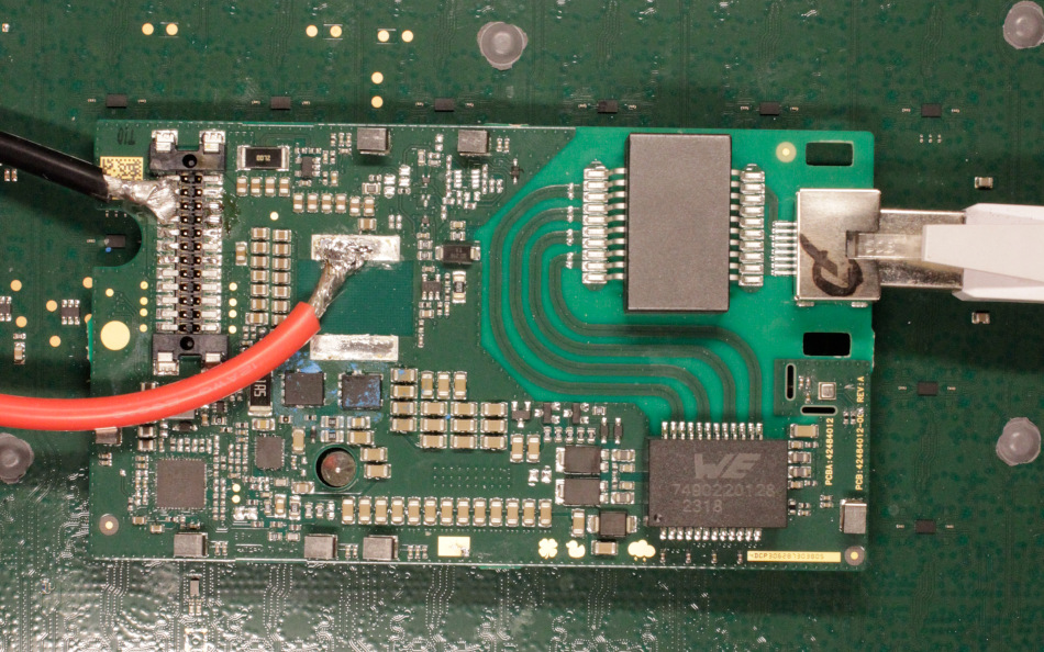
Power supply board
Let’s look at the power supply board components.
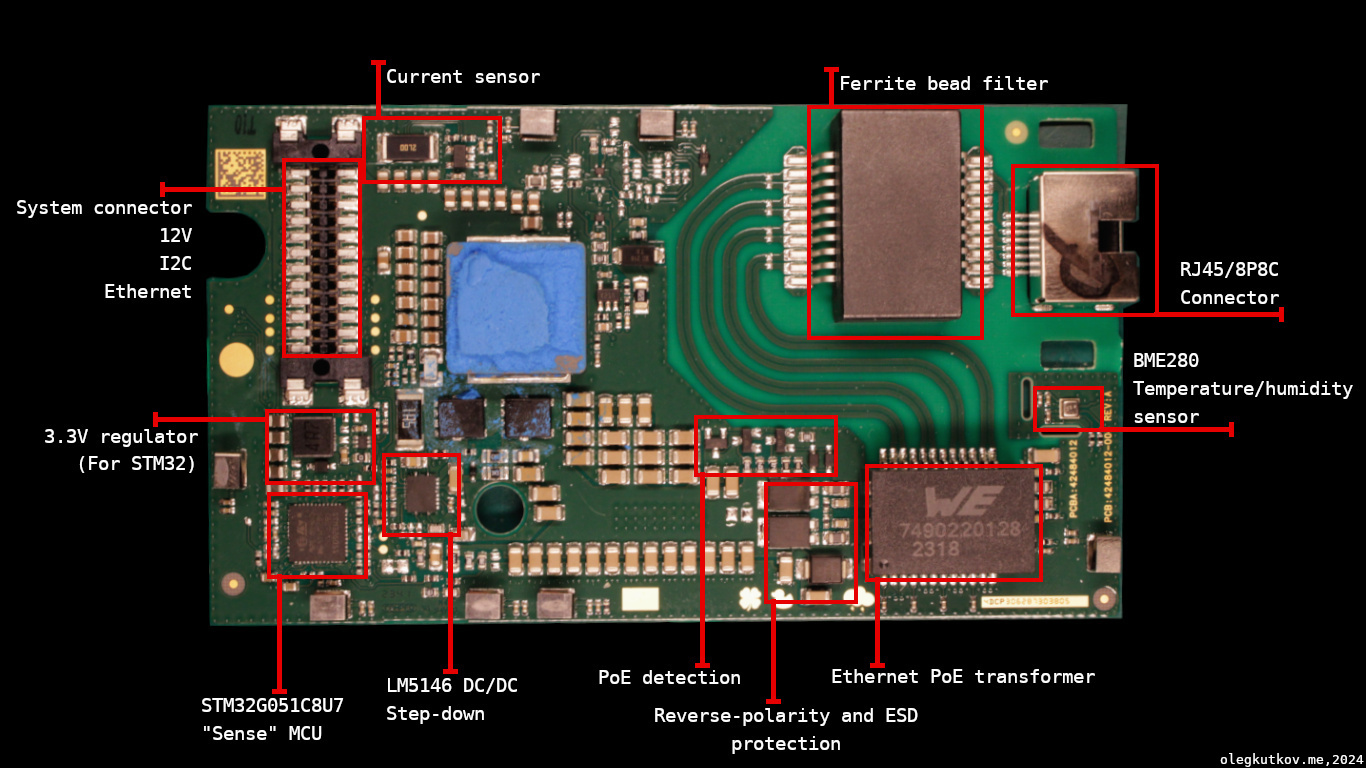
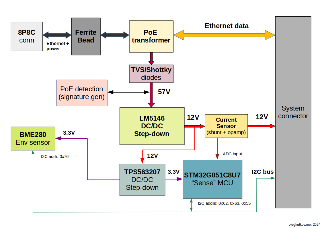
The input jack is connected to the Ethernet magnetics via a PCB-mounted ferrite bead.
Ethernet data from the transformer is routed directly to the system connector. TVS diodes are placed on the primary PCB. Supply voltage passes a few diodes that protect from reverse polarity and voltage spikes.
The PoE detection circuit generates a signature that helps the PSU (router) detect connected Dishy and provide a 57V supply. An upcoming article will discuss this further.
The primary step-down is built around the well-known LM5146, equivalent to the L3751 used in the REV3 terminal. The layout and principle of the operation are the same.
The STM32 MCU (SpaceX calls it “sense” mcu) monitors voltage and current incoming. It runs protected SpaceX firmware and is accessible via the terminal’s I2C bus.
A special script in the Dishy firmware checks controller presence and updates its firmware if necessary.
Depending on the current operating mode, the controller uses different addresses on the I2C bus:
– Bootloader: 0x62
– Boot ROM: 0x63
– SpaceX application: 0x55
The current sensor is based on a low-value resistor and operation amplifier and is connected to the MCU ADC input.
Bosch BME280 temperature/humidity sensor is configured to address 0x76 and connected to the same I2C bus. But it seems currently unused (as of the end of July 2024). At least I haven’t noticed any requests to the sensor address.
Here is a block diagram of the power supply board:
You may have noticed an additional current shunt near the inductor. However, it seems connected only to the unpopulated area on the top of the board. I have no idea why it’s there.
System connector
This is the pinout of the connector:
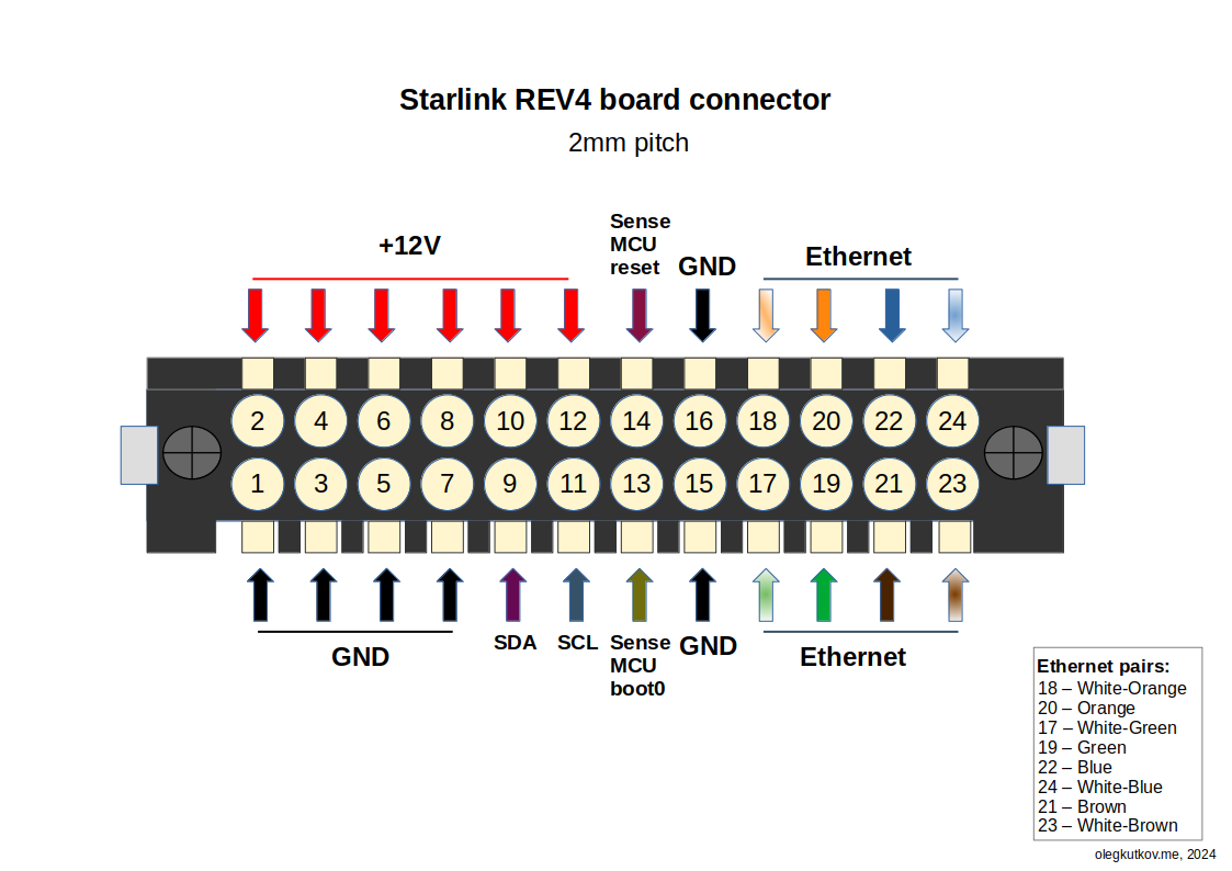
SDA/SCL pins are connected directly to the Starlink SoC and used for communication with the sense MCU and BME280.
Reset and Boot0 are simple GPIO lines of the SoC that reset the sense MCU and switch it to bootloader mode. You can ignore these lines.
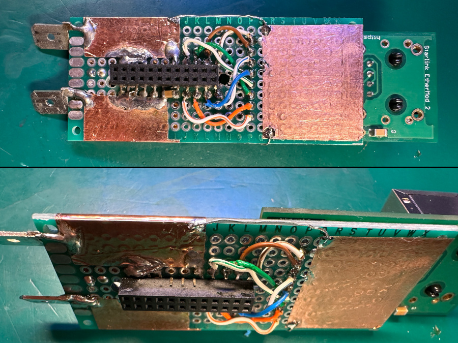
Ethernet lines are intended to be connected to the Ethernet transformer. The colors are for reference.
Please never connect this bus directly to an Ethernet cable.
Lame 12V mod
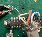
The easiest way to convert to 12V is to remove the big inductor and connect wires directly to the GND and 12V bus on the PCB.
Nothing more is required. It will run fine on 12V and the sense MCU will be powered and accessible.
Please always connect a positive wire to the inductor’s pad. This will help optimize the buffer capacitors’ usage.
The negative wire should be soldered directly to the connector. This will bypass the current sensor and eliminate any overcurrent alerts and triggers.
The allowable voltage range is 10-16V. It will survive voltage spikes around 17V, but I wouldn’t recommend running it long on higher voltages.
Please note there is no reverse-polarity protection. Wrong polarity will kill your Dishy.
Running without the power supply board
It’s possible to run the terminal without this power supply board. The current firmware doesn’t care about the absence of the sense MCU.
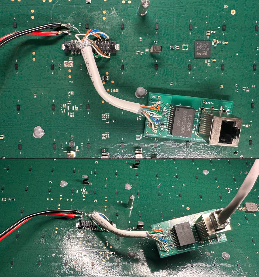
As an experiment, I used my EtherMod board, which was hardwired to the PCB. It works without any issues.
A note about testing without the router and App
The web interface on 192.168.100.1/dishy.starlink.com has been dead for a long time. SpaceX didn’t have the resources to support it, so they abandoned it.
Direct access to the gRPC API is the easiest way to test Dishy running without the router and mobile App. We can use grpcurl for this.
Getting the current status of the terminal (a.k.a. debug data):
grpcurl -plaintext -d {\"get_status\":{}} 192.168.100.1:9200 SpaceX.API.Device.Device/Handle
The most critical sections in the output:
Ethernet is running at full speed:
"ethSpeedMbps": 1000,
All components are up and running:
"readyStates": {
    "scp": true,
    "l1l2": true,
    "xphy": true,
    "aap": true,
    "rf": true
},
GPS is ok:
"gpsStats": {
    "gpsValid": true,
    "gpsSats": 7
},
The Starlink terminal can enter the network and reach the ground PoP:
"initializationDurationSeconds": {
    "burstDetected": 63,    <<<< Detect signal burst from the satellite
    "firstCplane": 77,      <<<< Received control data package
    "firstPopPing": 108,    <<<< Successful ping of the ground PoP
    "gpsValid": 71,
    "initialNetworkEntry": 75,   <<<< Entered the network
    "networkSchedule": 82,  <<<< Received network schedule from the SpaceX "orchestrator"
    "rfReady": 50
},
REV4 Power Hat
I built a better prototype to prove the concept.
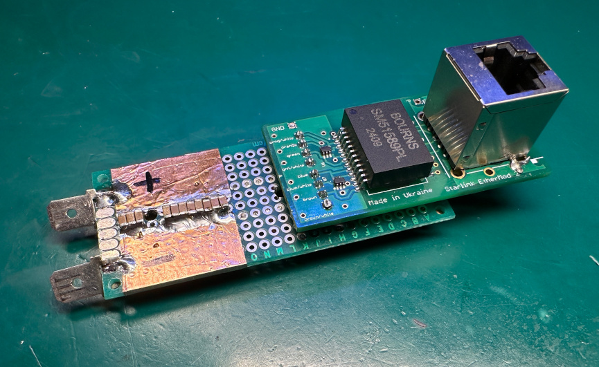
The central element is the same EtherMod. The ceramic capacitor array helps eliminate voltage drops when long wires are used.
Fits and works nicely:
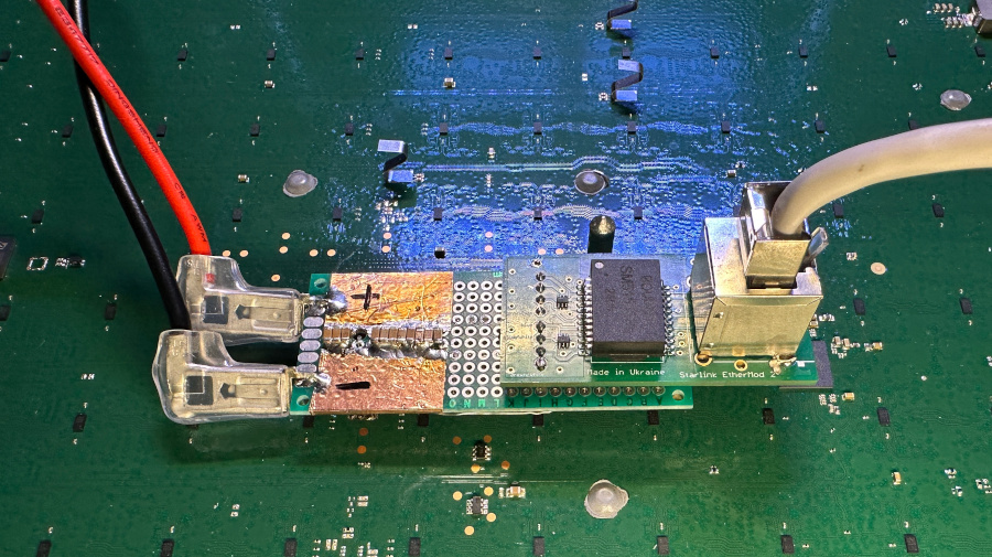
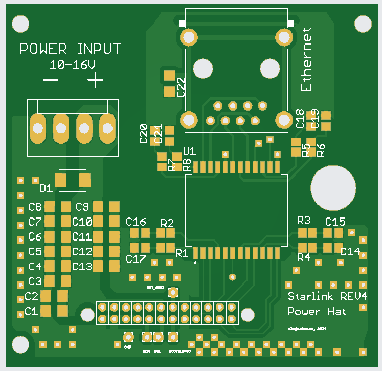
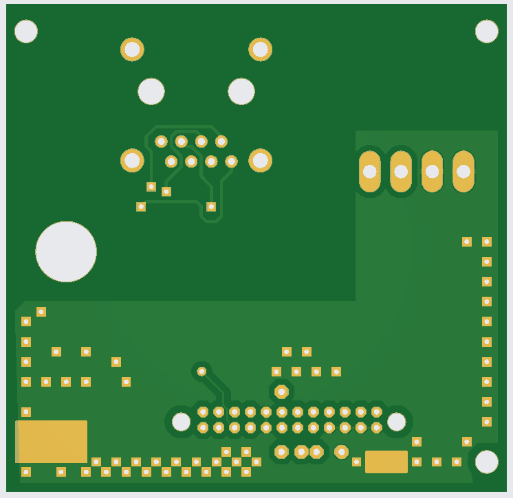
Finally, I designed a custom “power hat” PCB.
The schematic is below. You may have noticed the lack of ESD protection. We don’t need these extra components since they are on the primary PCB.
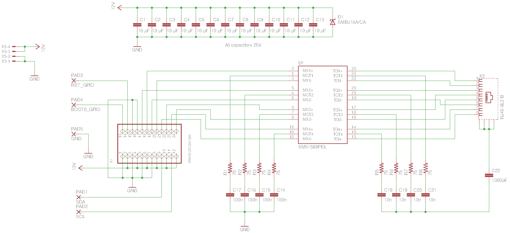
The PCB is double-sided, but all components are only on the top side.
Current consumption
Lower voltage means higher current, and REV 4 is power-hungry. Without heaters, you should expect 8+ A spikes over the 12V bus.
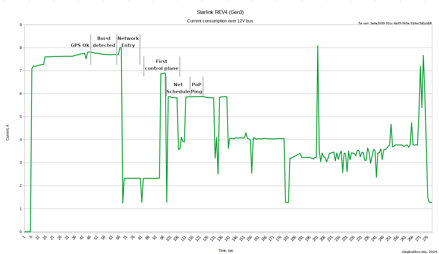
When heating, the current consumption may exceed 15A with active data transmission.
Despite this, 12V conversion may save you some percent of the power.
Thanks for reading!
Boa tarde amigo usando cabo de 5 metros 2,5 é preciso colocar capacitor eletrolitico. Igual na rav3
In the case of instability. You can try to run without the additional capacitor.
Dá para alimentar router da gen3, em linha12v direto?
I really admire your work, congratulations. My question, connecting the 12v directly to the coil that will be removed, how can I connect the original router to the antenna?
I recommend to use any other good router.
Hi Oleg,
Really appreciate the work you are doing!
Do you have any picture and block diagram of the Starlink REV4 router and its PoE PSE circuit?
Is it possible to connect the router? 12 volts directly or do I need a converter?
You can connect directly any router you want.
Would you have the connection diagram to connect the original gen 3 router, at 12 volts, or do I need a stepup from 12 v to 52 v
I think you should be power it directly from 12V without step-up.
Where do I connect the 12 volts to the router directly? of the main coil?
Input DC jack.
Якщо заживити антену від 12 вольт, та не викорустовувати роутер старлінку, а взяти інший. Чи буде скорость віддачі не блокуватися до 20-40 мгбит?
Бо ось наприклад експеримент, я вмикаю в рідний роутер старлінка кабель інета з 900/900 мбитс замість антени, а роутер робе відачу тільки 20 мегабіт. То можлило швидкість віддачі само в роутері такач а ні в тарелці?
Для живлення антени від 12 вольт, без рідного роутера, треба використовувати PoE інжектор (зроблений для старлінка) та DC-DC конвертер. Або інжектор з вбудованим DC-DC. Наприклад останні YaoSheng. Спитати можна тут: 0634448181
Швидкість не буде ніяк лімітуватись, тарілка такого не робить.
WELCOME TO EVERYONE WHO IS LOOKING FOR A SOLUTION TO USE THE Gen 3 ROUTER, I WOULD LIKE TO SET UP A GROUP ON TELEGRAM, I HAVE THE WHOLE BOARD VIEW IN DIODE SCALE AND WORKING VOLTAGES, BUT I HAVE SOME DIFFICULTIES IN SOLVING THE PROBLEM OF THE ROUTER TO PUT THE ANTENNA IN A CASE AND USE IN CARS, CALL ME ON TELEGRAM +5567991881921
Você já fez o grupo do telegram ?
Does the original router work with 12 volts directly from the DC jack? The power supply works with 52 V
I love the work you do and I did this mod on the REV3 antenna. I have yet to application test it though. In my line of work, we have a lot of POE converted REV3 antennas but they all seem to have an issue with cutting out. Looking at the number of connected satellites has shown that it is not a connection issue but I think it is a noise interference from the cheap step up converters. Once I can test your mod in the field, I will have a definitive answer. I would also like to talk to you about the high performance dish and whether or not you have been able to pull one of those apart.
E possível fazer swap de memória da gen 2 para Starlink mini?
A mini arquitetura não é compatível com terminais mais antigos.
分析得太好了.讚!
About the 24 pin connector,
Apparently I found 3 of those inside my broken Mini 0801 dashcam!
I don’t have the dish yet, so I can’t confirm it, but if anyone has one of those laying around, it cloud help!
Добрий день, Олег. Дякую за статтю.
При використанні стороннього роутера, наприклад, MikroTik, після налаштування антени перестає працювати оригінальний додаток Starlink та Star Debug.
Чи є у вас рішення для цієї проблеми?
Дякую заздалегідь!
Good afternoon, Oleh. Thank you for the article.
When using a third-party router, such as MikroTik, after configuring the antenna, the original Starlink and Star Debug applications stop working.
Do you have a solution for this issue?
Thank you in advance!
Вітаю. Для того щоб працював додаток – в налаштуваннях MikroTik треба додати статичний маршрут до 192.168.100.1
Додаток потребує доступа до цієї адреси. За замовчанням – весь трафик завертається просто в інтернет.
Boa tarde meu amigo vc teria a antena v2 e v3 mapeada tipo tensoes e condução reversas ??
Hello. I’m afraid I do not entirely understand your question. Do you mean voltages on the antenna PCB?
Do you have any solutions for my mini router that isn’t giving a Wi-Fi signal?
Regarding the black and red connectors, these are the external 12-volt radiator terminals. Now, where do they connect?
Do you have any schematic diagram for starlink Gen 3 please