In the previous article, I describe a low noise amplifier for the 21cm band.
Today I want to show you a construction of the dish antenna where this amplifier was used.
Most optimal, efficient, and easy to build is a classic dish antenna that consists of an actual dish that acts like a mirror and some receiver at the focal point.
Unfortunately, a 21 cm band requires a quite massive receiver so you can’t use a small dish. Also, you need to use a bigger antenna to achieve some reasonable resolution.
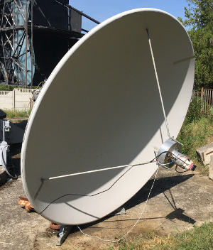
My antenna is 3m in diameter and it was used for satellite communication by some ISP

The maximum angular resolution of this single antenna can be calculated by this formula:

Where λ is a wavelength (0.21 meters) and D is the diameter of the mirror (3 meters).
My antenna came as just a dish without any receivers and even without stands to secure the receiver at the focal point.
I needed to create this stands from scratch. The ideal material is an aluminum tube of a good reasonable diameter. But before cutting tubes it’s a good idea to figure out where is the focal plane of this mirror.
The focal distance of this antenna was totally unknown. There are a few ways to find this distance.
The first way is the calculation. For the parabola mirror you can find focal distance using this formula:
![]()
Where D is the diameter of the mirror and h it’s the depth of this mirror. Don’t forget to use the same magnitudes in both parts of the formula!
So I found the focal distance of my antenna.
The diameter is 300 centimeters and the depth is 47 centimeters.
Focal distance = 300*300 / 16 * 47 = 9000/752 = 119.68 centimeters.
Another way is experimental. You can use a strong source of light (the Sun), direct antenna to this source, and manually find a point of the max intensity. Yeah, this can be very tricky for such a big antenna and for the light.
In early experiments, I’m using the Sun as a strong source of wideband radio noise. As control receiver was used cheap satellite tv LNB and analog satellite finder with an arrow indicator.

Antenna construction
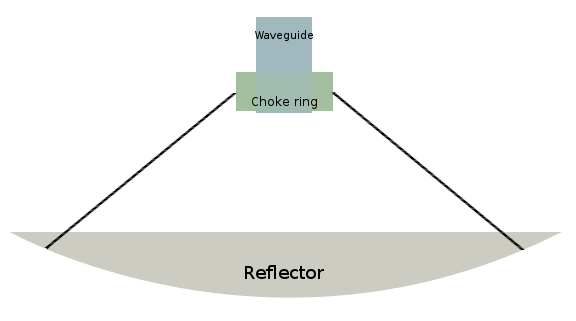
To achieve maximum performance of the whole antenna we need to place complex construction at the focal plane.
This construction consists of the waveguide which is actually a tube with length and diameter selected for the band and a choke ring.
The purpose of the choke ring is to use the maximum area of the dish without losing incoming signals and without acquiring terrestrial noise from the dish edges.
This how actual construction looks like:

There are few formulas to calculate the length and diameter of the waveguide and diameter, depth, and placement of the choke ring.
Waveguide diameter has an impact on minimal and maximal wavelength, acts as a bandpass filter.
Please note that the length of the wave inside the waveguide is longer than in open air.
You can find the minimal cutoff frequency in GHz from diameter using this formula:
![]()
To find maximal frequency just multiply Flcut by 1.3065
I chose waveguide diam as 14.5 centimeters so my cutoff frequencies are 1.21 GHz and 1.59 GHz. This is very good, maximal resonance is somewhere in between which is optimal.
The wavelength inside the waveguide can be calculated using this formula:
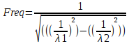
Where λ1 is the wavelength in an open-air – 21 centimeter and λ2 is a minimum cutoff frequency which was calculated above (24.7 centimeters in my case). So with a waveguide diameter of 14.5 cm, the internal wavelength is 40.8 centimeters!
The total length of the waveguide can be set as a minimum two-quarter wavelength inside the waveguide, the optimal value is three quarters.
So the length of the waveguide 40,8÷4×3 = 30.6 centimeters.
Now let’s talk about the choke ring.
Depth (h) of the choke ring can be calculated easily:

Where λ is again our wavelength – 21 centimeter. So the depth of the choke ring is 10.5 centimeters.
Choke ring diameter:
![]()
Where h is the depth of the choke ring and D is the diameter of the waveguide.
The position of the choke ring can be obtained experimentally. I believe that optimal is when the outer edge of the ring and the outer edge of the waveguide at the same level.
You can use this electronic table to easily calculate all the values above including the position of the choke ring:
The actual receiving element is a probe placed inside the waveguide. This is a copper rod of small diameter (thick wire can be used) which is soldered on an N-type RF connector. This probe should be placed in one of the maximum energy points inside the waveguide. See the picture below.
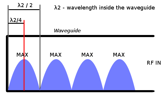
Probe placement in my case is 10.2 centimeters from the waveguide’s dead end.
Probe length should be 1/4 of the open-air wavelength or 21/4 = 5.25 cm.
Construction of the probe mounted on RF N-type connector and how it looks inside the waveguide:
External view and probe connection to the LNA using high quality and low loss 50-ohm cable:
Adjustments and testing
All this construction requires some calibration. As you can find in the electronic table above – the focal plane is placed somewhere inside the waveguide. The position of the whole waveguide with the choke ring should be adjusted to achieve the maximum signal level. As a “reference” signal source you can use the Sun or artificial satellites, like INMARSAT.
As you can on the photo in the beginning my mounting system with the stands allows us to move and align this receiver with a few screw-nuts.
The first successful test was in August 2017.
In the video below you can wideband noise from the Sun and signals from the INMARSAT satellites.
I’m moving this antenna manually to slide on all these objects.
As the receiver can be used a wide range of the SDR, RTL-SDR with a few HW mods (cooling + power filtering), for example.
Hydrogen line 21 cm is extra weak so it’s really hard to get and collect the signal.
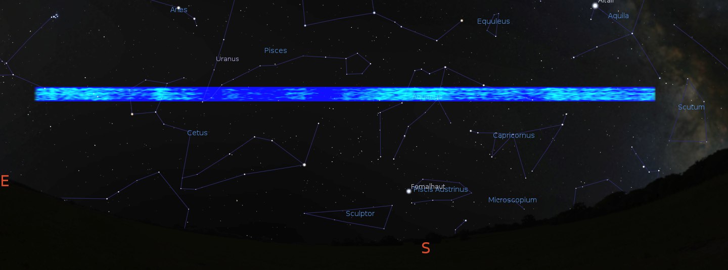
I spent some time scanning the narrow line on the night sky. All collected data were summarized and I’ve got this picture of the signal fluctuation. The picture was projected to the actual view of the sky at that time.
Few notes about polarization of the signal.
Polarization is actually relative thing and depends on the actual position of the transmitter and receiver and where is “up” and “down”. It’s very important for the artificial signals.
In case of space signals vertical or horizontal polarization doesn’t make sense so you can place you probe in the waveguide at the any angle you wish. All this natural signals can be even non-polarized or partially polarized or polarized by the some way.
Polarization factor is very important for astrophysics and if you wish to measure polarization you need to build polarimeter.
Polarimeter has the same construction but contains two probes in the waveguide. This probes is placed perpendicular to each other. Getting and comparing signal from the both probes you can estimate polarization factor and even type of the polarization
Another interesting experiment (with the new LNA) is acquisition signals from the Moon.
You can enable English subtitles in the video below.
Important information:
Unfortunately, I had to abandon this antenna and this project.
I moved from Crimea (to mainland Ukraine) due to political, social, and economic reasons. It was a hard but important decision.
This antenna is still around but no one is using it. Sad.
Thanks for reading!
My method to find dish focal point is to make an aluminum tape cross on the dish and then point at the sun as you have. It’s still tricky but the increased reflectance and structure of the cross of light helps in finding the focal point.
Yes, it’s very good idea!
Alternatively, as done by telescope mirror grinders, Spray the dish with soapy water and while still wet,
point at the sun and find the focus. The dish accuracy will be determined this way as well. A perfect
mirror of your sort should focus to a bright spot less than a cm in diameter.
eric-
WN7WNL
I already wanted to mount the antenna inside the waveguide. This plug is very mechanically convenient for this.
But I really don’t like the difference in the diameters of the antenna wire and the plug.
Is it better not to do this?
Is the difference in diameters really very important in this case?
https://ibb.co/mX8cd2v
I decided not to risk with different diameters of the antenna and plug.
In radio astronomy, every little thing can become fatal! 🙂
I used such connectors.
https://ibb.co/X5Fyy5F
My antenna wire came in very tightly.
I solder the other end of the antenna directly into the LNB, without the plugs.
Redesigned internal antennas.
https://ibb.co/vx4xg1x
This is how they look in place in the waveguides.
https://ibb.co/7S0VS7z
https://ibb.co/m0d46wL
Horizontal and vertical polarization.
Looks good
But it’s better to move backplate corner mounts outside the waveguide. Also, it’s better to use more than two. There is should be good electrical contact.